
Specifications


90 JN-DS-JN5148-001 1v9 © NXP Laboratories UK 2013
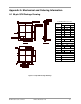
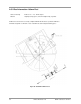
B.2 32MHz Oscillator
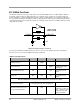
The JN5148 contains the necessary on-chip components to build a 32 MHz reference oscillator with the addition of
an external crystal resonator, two tuning capacitors. The schematic of these components are shown in Figure 58.
The two capacitors, C1 and C2, will typically be 15pF ±5% and use a COG dielectric. For a detailed specification of
the crystal required and factors affecting C1 and C2 see Appendix B.1. As with all crystal oscillators the PCB layout is
especially important, both to keep parasitic capacitors to a minimum and to reduce the possibility of PCB noise being
coupled into the oscillator.
XTALOUT
C2
C1
R1
XTALIN
JN5148
Figure 58: Crystal oscillator connections
The clock generated by this oscillator provides the reference for most of the JN5148 subsystems, including the
transceiver, processor, memory and digital and analogue peripherals.
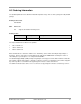
32MHz Crystal Requirements
Parameter Min Typ Max Notes
Crystal Frequency 32MHz
Crystal Tolerance 40ppm Including temperature
and ageing
Crystal ESR Range (Rm)
10Ω
60Ω
See below for more
details
Crystal Load Capacitance
Range (CL)
6pF 9pF 12pF
See below for more
details
Not all Combinations of Crystal Load Capacitance and ESR are Valid
Recommended Crystal
Load Capacitance 9pF and max ESR 40 Ω
External Capacitors (C1 & C2)
For recommended Crystal
15pF
CL = 9pF, total external
capacitance needs to be
2*CL. , allowing for stray
capacitance from chip,
package and PCB