
Specifications


© NXP Laboratories UK 2013 JN-DS-JN5148-001 1v9 45
13 Serial Communications
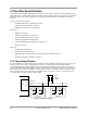
The JN5148 has two independent Universal Asynchronous Receiver/Transmitter (UART) serial communication
interfaces. These provide similar operating features to the industry standard 16550A device operating in FIFO mode.
Each interface performs serial-to-parallel conversion on incoming serial data and parallel-to-serial conversion on
outgoing data from the CPU to external devices. In both directions, a 16-byte deep FIFO buffer allows the CPU to
read and write multiple characters on each transaction. This means that the CPU is freed from handling data on a
character-by-character basis, with the associated high processor overhead. The UARTs have the following features:
• Emulates behaviour of industry standard NS16450 and NS16550A UARTs
• 16 byte transmit and receive FIFO buffers reduce interrupts to CPU, with direct access to fill levels of each
• Adds / deletes standard start, stop and parity communication bits to or from the serial data
• Independently controlled transmit, receive, status and data sent interrupts
• Optional modem flow control signals CTS and RTS
• Fully programmable data formats: baud rate, start, stop and parity settings
• False start bit detection, parity, framing and FIFO overrun error detect and break indication
• Internal diagnostic capabilities: loop-back controls for communications link fault isolation
• Flow control by software or automatically by hardware
Processor Bus
Divisor
Latch
Registers
Line
Status
Register
Line
Control
Register
FIFO
Control
Register
Receiver FIFO
Transmitter FIFO
Baud Generator
Logic
Transmitter Shift
Register
Receiver Shift
Register
Transmitter
Logic
Receiver
Logic
RXD
TXD
Modem
Control
Register
Modem
Status
Register
Modem
Signals
Logic
RTS
CTS
Interrupt
ID
Register
Interrupt
Enable
Register
Interrupt
Logic
Internal
Interrupt
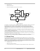
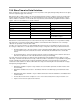
Figure 33: UART Block Diagram
The serial interface contains programmable fields that can be used to set number of data bits (5, 6,7 or 8), even, odd,
set-at-1, set-at-0 or no-parity detection and generation of single or multiple stop bit, (for 5 bit data, multiple is 1.5 stop
bits; for 6, 7 or 8 data bits, multiple is 2 bits).
The baud rate is programmable up to 1Mbps, standard baud rates such as 4800, 9600, 19.2k, 38.4k etc. can be
configured.
For applications requiring hardware flow control, two control signals are provided: Clear-To-Send (CTS) and Request-
To-Send (RTS). CTS is an indication sent by an external device to the UART that it is ready to receive data. RTS is
an indication sent by the UART to the external device that it is ready to receive data. RTS is controlled from software,
while the value of CTS can be read. Monitoring and control of CTS and RTS is a software activity, normally
performed as part of interrupt processing. The signals do not control parts of the UART hardware, but simply indicate
to software the state of the UART external interface. Alternatively, the Automatic Flow Control mode can be set