
Specifications


© NXP Laboratories UK 2013 JN-DS-JN5148-001 1v9 27
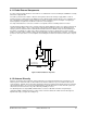
8.1.1 Radio External Components
In order to realise the full performance of the radio it is essential that the reference PCB layout and BOM are carefully
followed. See Appendix B.4.
The radio is powered from a number of internal 1.8V regulators fed from the analogue supply VDD1, in order to
provide good noise isolation between the digital logic of the JN5148 and the analogue blocks. These regulators are
also controlled by the baseband controller and protocol software to minimise power consumption. Decoupling for
internal regulators is required as described in section 2.2.1, Power Supplies
For single ended antennas or connectors, a balun is not required, however a matching network is needed.
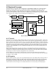
The RF matching network requires three external components and the IBIAS pin requires one external component as
shown in schematic in B.4.1. These components are critical and should be placed close to the JN5148 pins and
analogue ground as defined in Table 8: JN5148 Printed Antenna Reference Module Components and PCB Layout
Constraints. Specifically, the output of the network comprising L2, C1 and L1 is designed to present an accurate
match to a 50 ohm resistive network as well as provide a DC path to the final output stage or antenna. Users wishing
to match to other active devices such as amplifiers should design their networks to match to 50 ohms at the output of
L1
R1 43K
IBIAS
C20 100nF
L2 2.7nH
VB_RF
VREF
VB_RF2
RF_IN
C3 100nF
C12 47pF
VB_RF1
C1 47pF
L1 5.6nH
To Coaxial Socket
or Integrated Antenna
VB_RF
Figure 15 External Radio Components
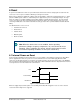
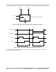
8.1.2 Antenna Diversity
Support is provided for antenna diversity. Antenna diversity is a technique that maximises the performance of an
antenna system. It allows the radio to switch between two antennas that have very low correlation between their
received signals. Typically, this is achieved by spacing two antennas around 0.25 wavelengths apart or by using two
orthogonal polarisations. So, if a packet is transmitted and no acknowledgement is received, the radio system can
switch to the other antenna for the retry, with a different probability of success.
The JN5148 provides an output (ADO) on DIO12 that is asserted on odd numbered retries and optionally its
complement (ADE) on DIO13, that can be used to control an antenna switch; this enables antenna diversity to be
implemented easily (see Figure 16 and Figure 17).