
User's Manual


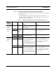
Table Of Contents
- SECTION 1 General Information
- SECTION 2 InterReach™ Unison System Description
- SECTION 3 Unison Main Hub
- SECTION 4 Unison Expansion Hub
- SECTION 5 Unison Remote Access Unit
- SECTION 6 Installing Unison Components
- 6.1 Installation Requirements
- 6.2 Safety Precautions
- 6.3 Preparing for System Installation
- 6.4 Unison Component Installation Procedures
- 6.5 Starting and Configuring the System
- 6.6 Interfacing a Main Hub to a Base Station or Roof-top Antenna
- 6.7 Connecting Contact Alarms to a Unison System
- SECTION 7 Installing and Using the AdminManager Software
- SECTION 8 Designing a Unison Solution
- 8.1 Maximum Output Power per Carrier at RAU
- 8.2 Estimating RF Coverage
- 8.3 System Gain
- 8.4 Link Budget Analysis
- 8.4.1 Elements of a Link Budget for Narrowband Standards
- 8.4.2 Narrowband Link Budget Analysis for a Microcell Application
- 8.4.3 Elements of a Link Budget for CDMA Standards
- 8.4.4 Spread Spectrum Link Budget Analysis for a Microcell Application
- 8.4.5 Considerations for Re-Radiation (over-the-air) Systems
- 8.5 Optical Power Budget
- 8.6 Connecting a Main Hub to a Base Station
- 8.7 Designing for a Neutral Host System
- SECTION 9 Replacing Unison Components in an Operating System
- SECTION 10 Maintenance, Troubleshooting, and Technical Assistance
- APPENDIX A Cables and Connectors
- APPENDIX B Compliance
- APPENDIX C Glossary

Installing Unison Components PRELIMINARY
6-18 InterReach Unison User Guide and Reference Manual
PN 8700-10
620003-0
6.4.2.1 Troubleshooting Expansion Hub LEDs During Installation
• All Expansion Hub LINK and E-HUB/RAU LEDs with RAUs connected should indi-
cate Green/Red, which indicates that the RAU is powered on and communication
has been established.
• The Expansion Hub
UL STATUS LED should be Green.
6.4.2.2 Installing Expansion Hubs in a Neutral Host System
Installing Expansion Hubs in a neutral host system is the same as described in
Section 6.4.2 on page 6-13.
If rack-mounting the Expansion Hubs, we recommend mounting all neutral host sys-
tem hubs in the same rack(s) or location, grouped by frequency or carrier. For exam-
ple, group the Expansion Hubs for the iDEN carrier(s) together, then the 800 MHz
cellular carrier(s), and so on.
Table 6-5 Troubleshooting Expansion Hub LEDs During Installation
During
Installation LED State Action Impact
Expansion Hub
power is On and
no RAUs are
connected
POWER
Off Check AC power; check that the
Expansion Hub power-on switch
is on; replace the Expansion Hub.
Expansion Hub is not powering on.
LINK
LEDs
on but
didn’t
blink
through
all states
Replace the Expansion Hub. Microcontroller not resetting properly;
flash memory corrupted.
E-HUB/RAU
UL STATUS
Red Replace the Expansion Hub. The Expansion Hub laser is not opera-
tional; no uplink between the Expansion
Hub and Main Hub.
LINK
Red Port unusable; replace the Expan-
sion Hub when possible.
Current sensor fault; do not use the port.
E-HUB/RAU
Off
Connect RAU
LINK
Off Check the Cat-5/6 cable. Power is not getting to the RAU.
E-HUB/RAU
Off
LINK
Red Test the Cat-5/6 cable. If the cable
tests OK, try another port. If the
second port’s LEDs are Red/Off,
replace the RAU. If the second
RAU doesn’t work; replace the
Expansion Hub.
Power levels to RAU are not correct;
communications are not established.
If the second port works, flag the first
port as unusable; replace EH when possi-
ble.
E-HUB/RAU
Off