
User's Manual
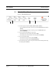


Table Of Contents
- SECTION 1 General Information
- SECTION 2 InterReach™ Unison System Description
- SECTION 3 Unison Main Hub
- SECTION 4 Unison Expansion Hub
- SECTION 5 Unison Remote Access Unit
- SECTION 6 Installing Unison Components
- 6.1 Installation Requirements
- 6.2 Safety Precautions
- 6.3 Preparing for System Installation
- 6.4 Unison Component Installation Procedures
- 6.5 Starting and Configuring the System
- 6.6 Interfacing a Main Hub to a Base Station or Roof-top Antenna
- 6.7 Connecting Contact Alarms to a Unison System
- SECTION 7 Installing and Using the AdminManager Software
- SECTION 8 Designing a Unison Solution
- 8.1 Maximum Output Power per Carrier at RAU
- 8.2 Estimating RF Coverage
- 8.3 System Gain
- 8.4 Link Budget Analysis
- 8.4.1 Elements of a Link Budget for Narrowband Standards
- 8.4.2 Narrowband Link Budget Analysis for a Microcell Application
- 8.4.3 Elements of a Link Budget for CDMA Standards
- 8.4.4 Spread Spectrum Link Budget Analysis for a Microcell Application
- 8.4.5 Considerations for Re-Radiation (over-the-air) Systems
- 8.5 Optical Power Budget
- 8.6 Connecting a Main Hub to a Base Station
- 8.7 Designing for a Neutral Host System
- SECTION 9 Replacing Unison Components in an Operating System
- SECTION 10 Maintenance, Troubleshooting, and Technical Assistance
- APPENDIX A Cables and Connectors
- APPENDIX B Compliance
- APPENDIX C Glossary

PN 8700-10 Help Hot Line (U.S. only): 1-800-530-9960 3-11
620003-0
PRELIMINARY Main Hub Specifications
3.4 Main Hub Specifications
Table 3-3 Main Hub Specifications
Specification Description
Enclosure Dimensions (H
× W × D): 44.5 mm × 438 mm × 305 mm
(1.75 in. × 17.25 in. × 12 in.)
Weight < 3 kg (< 6.5 lb)
Operating Temperature 0° to +45°C (+32° to +113°F)
Non-operating Temperature –20° to +85°C (–4° to +185°F)
Operating Humidity, non-condensing 5% to 95%
External Alarm Connector
(contact closure)
1 9-pin D-sub, female
Serial Interface Connector 1 9-pin D-sub, male
Fiber Connectors 4 Pair, SC/APC
RF Connectors 2 N-type, female
LED Fault and Status Indicators Unit Status (1 pair):
•Power
• Main Hub Status
Downstream Unit/Link Status (1 pair per fiber port):
•Link
•E-Hub/RAU
AC Power Rating: 100–240V, 0.5A, 50–60 Hz
Operating Range: 85–250V, 2.4–0.8A, 47–63 Hz
Power Consumption (W) 30
MTBF 106,272 hours