
User's Manual

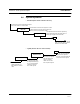

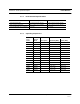

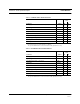


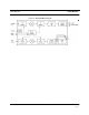
Table Of Contents
- SECTION 1 General Information
- SECTION 2 InterReach™ Unison System Description
- SECTION 3 Unison Main Hub
- SECTION 4 Unison Expansion Hub
- SECTION 5 Unison Remote Access Unit
- SECTION 6 Installing Unison Components
- 6.1 Installation Requirements
- 6.2 Safety Precautions
- 6.3 Preparing for System Installation
- 6.4 Unison Component Installation Procedures
- 6.5 Starting and Configuring the System
- 6.6 Interfacing a Main Hub to a Base Station or Roof-top Antenna
- 6.7 Connecting Contact Alarms to a Unison System
- SECTION 7 Installing and Using the AdminManager Software
- SECTION 8 Designing a Unison Solution
- 8.1 Maximum Output Power per Carrier at RAU
- 8.2 Estimating RF Coverage
- 8.3 System Gain
- 8.4 Link Budget Analysis
- 8.4.1 Elements of a Link Budget for Narrowband Standards
- 8.4.2 Narrowband Link Budget Analysis for a Microcell Application
- 8.4.3 Elements of a Link Budget for CDMA Standards
- 8.4.4 Spread Spectrum Link Budget Analysis for a Microcell Application
- 8.4.5 Considerations for Re-Radiation (over-the-air) Systems
- 8.5 Optical Power Budget
- 8.6 Connecting a Main Hub to a Base Station
- 8.7 Designing for a Neutral Host System
- SECTION 9 Replacing Unison Components in an Operating System
- SECTION 10 Maintenance, Troubleshooting, and Technical Assistance
- APPENDIX A Cables and Connectors
- APPENDIX B Compliance
- APPENDIX C Glossary

PN 8700-10 Help Hot Line (U.S. only): 1-800-530-9960 2-15
620003-0
PRELIMINARY RF End-to-End Performance
Table 2-5 DCS RF End-to-End Performance
Parameter Typical
Link
UL DL
Average gain with 75 m Cat-5/6 at 25°C (77°F)*
*System output gain: 0 to 15 dB, adjustable in 1 dB steps.
The gain of individual RAUs can be attenuated 0 to 10 dB, adjustable in one step.
15 dB
Uplink Ripple with 75 m Cat-5/6 5.5 dB
Downlink Ripple with 75 m Cat-5/6 3 dB
Output IP3 36.5 dBm
Input IP3 –16 dBm
Output 1 dB Compression Point 24.5 dBm
GSM output power per carrier when 16 carriers are present 5.0 dBm
Noise Figure 1 MH-1 EH-8 RAUs 17 dB
Noise Figure 1 MH-4 EHs-32 RAUs 23 dB
Table 2-6 PCS RF End-to-End Performance
Parameter Typical
Link
UL DL
Average gain with 75 m Cat-5/6 at 25°C (77°F)*
*System output gain: 0 to 15 dB, adjustable in 1 dB steps.
The gain of individual RAUs can be attenuated 0 to 10 dB, adjustable in one step.
15 dB
Uplink Ripple with 75 m Cat-5/6 3 dB
Downlink Ripple with 75 m Cat-5/6 3 dB
Output IP3 36.5 dBm
Input IP3 –16 dBm
Output 1 dB Compression Point 24.5 dBm
TDMA output power per carrier when 16 carriers are present 4.0 dBm
GSM output power per carrier when 16 carriers are present 4.2 dBm
CDMA output power per carrier when 8 carriers are present 7.8 dBm
Noise Figure 1 MH-1 EH-8 RAUs 16 dB
Noise Figure 1 MH-4 EHs-32 RAUs 22 dB