
User's Manual

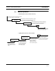

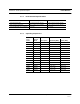

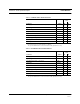

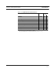

Table Of Contents
- SECTION 1 General Information
- SECTION 2 InterReach™ Unison System Description
- SECTION 3 Unison Main Hub
- SECTION 4 Unison Expansion Hub
- SECTION 5 Unison Remote Access Unit
- SECTION 6 Installing Unison Components
- 6.1 Installation Requirements
- 6.2 Safety Precautions
- 6.3 Preparing for System Installation
- 6.4 Unison Component Installation Procedures
- 6.5 Starting and Configuring the System
- 6.6 Interfacing a Main Hub to a Base Station or Roof-top Antenna
- 6.7 Connecting Contact Alarms to a Unison System
- SECTION 7 Installing and Using the AdminManager Software
- SECTION 8 Designing a Unison Solution
- 8.1 Maximum Output Power per Carrier at RAU
- 8.2 Estimating RF Coverage
- 8.3 System Gain
- 8.4 Link Budget Analysis
- 8.4.1 Elements of a Link Budget for Narrowband Standards
- 8.4.2 Narrowband Link Budget Analysis for a Microcell Application
- 8.4.3 Elements of a Link Budget for CDMA Standards
- 8.4.4 Spread Spectrum Link Budget Analysis for a Microcell Application
- 8.4.5 Considerations for Re-Radiation (over-the-air) Systems
- 8.5 Optical Power Budget
- 8.6 Connecting a Main Hub to a Base Station
- 8.7 Designing for a Neutral Host System
- SECTION 9 Replacing Unison Components in an Operating System
- SECTION 10 Maintenance, Troubleshooting, and Technical Assistance
- APPENDIX A Cables and Connectors
- APPENDIX B Compliance
- APPENDIX C Glossary

PN 8700-10 Help Hot Line (U.S. only): 1-800-530-9960 2-11
620003-0
PRELIMINARY System Specifications
2.7 System Specifications
2.7.1 Physical Specifications
Parameter Main Hub Expansion Hub Remote Antenna Unit
RF Connectors 2 N-type, female 8 shielded RJ-45, female
(Cat-5/6)
1 RJ-45, female (Cat-5/6)
1 SMA, male (coaxial)
External Alarm Connector
(contact closure)
1 9-pin D-sub, female — —
Serial Interface Connector 1 9-pin D-sub, male — —
Fiber Connectors 4 Pair, SC/APC 1 Pair, SC/APC —
LED Alarm and
Status Indicators
Unit Status (1 pair):
•Power
• Main Hub Status
Downstream Unit Status
(1 pair per fiber port):
•Link
•E-Hub/RAU
Unit Status (1 pair):
•Power
•E-Hub Status
Fiber Link Status (1 pair):
•DL Status
•UL Status
RAU/Link Status
(1 pair per RJ-45 port):
•Link
•RAU
Unit Status (1 pair):
•Link
•Alarm
AC Power (Volts) Rating: 100–240V, 0.5A,
50–60 Hz
Operating Range: 85–250V,
2.4–0.8A, 47–63 Hz
Rating: 115/230V, 5/2.5A,
50–60 Hz
Operating Range:
90–132V/170–250V
auto-ranging,
2.2–1.5A/1.2–0.8A, 47–63 Hz
—
DC Power (Volts) — — 36V
Power Consumption (W) 30 260 (includes 8 RAUs) 11
Enclosure Dimensions*
(height
× width × depth)
*Excluding angle-brackets for 19'' rack mounting of hubs.
44.5 mm × 438 mm × 305 mm
(1.75 in. × 17.25 in. × 12 in.)
89 mm × 438 mm × 305 mm
(3.5 in. × 17.25 in. × 12 in.)
44 mm × 305 mm × 158 mm
(1.7 in. × 12 in. × 6.2 in.)
Weight < 3 kg
(< 6.5 lb)
< 5 kg
(< 11 lb)
< 1 kg
(< 2 lb)
MTBF 106,272 hours 78,998 hours 282,207 hours