
User's Manual
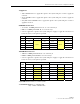
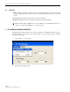
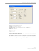
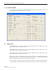


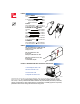
Table Of Contents
- ABOUT THIS MANUAL
- ADMONISHMENTS
- GENERAL SAFETY PRECAUTIONS
- FCC Compliance Statement
- STANDARDS CERTIFICATION
- LIST OF ACRONYMS AND ABBREVIATIONS
- SECTION 1: OVERVIEW
- SECTION 2: Installation
- SECTION 3: Graphical User Interface
- SECTION 4: GENERAL INFORMATION

ADCP-75-237 • Issue 1 • 8/2007 • Section 3: Graphical User Interface
Page 3-11
© 2007, ADC Telecommunications, Inc.
4.2 Rev Base Volt
Repeat the FWD Base Volt set-up for the Rev Base Volt (Reverse Base Voltage).
4.3 Band Selection
850MHz
1900MHz
A/B/C/x: 15MHz path band A, B, C, or no selection (x)
D/E/F/x: 5MHz path band D, E, F, or no selection (x)
Select to apply these options to the system and press “Apply” to apply the selections.
4.4 Attenuation Test: MGC / ALC Control
Press up/down arrow key to adjust the Manual Gain Control in 0.5dB increments.
Press up/down arrow key to adjust the Automatic Level Control in 0.5dB increments.
4.5 Gain Offset Box
FWD/REV gain offset can be changed in 0.5dB steps by using Up/Down Key.
4.6 Fwd PLL Attenuation Control
Each band can be selected to have 0.0~9.5dB attenuation. This function can test gain flatness.
Press “Write” to apply setting.
4.7 Rev Pll Attenuation Control
Same as FWD PLL Attenuation Control
If you have finished each function testing, press “Exit” to exit the testing mode and reset the
system.