
User's Manual

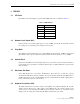
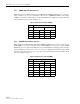
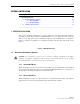

Table Of Contents
- ABOUT THIS MANUAL
- ADMONISHMENTS
- GENERAL SAFETY PRECAUTIONS
- FCC Compliance Statement
- STANDARDS CERTIFICATION
- LIST OF ACRONYMS AND ABBREVIATIONS
- SECTION 1: OVERVIEW
- SECTION 2: Installation
- SECTION 3: Graphical User Interface
- SECTION 4: GENERAL INFORMATION

ADCP-75-237 • Issue 1 • 8/2007 • Section 2: Installation
Page 2-3
© 2007, ADC Telecommunications, Inc.
2. Connect the alarm cable leads to the base station or site alarm system. Use either
“Normally Open” or “Normally Closed” contacts. shows the PDU alarm logic
3. Connect the other end of the alarm cable to the PDU “ALARM” connector.
4. Connect the power cable to the site DC power connector. (The power cable has three leads.
Red is positive, Black is negative, and Yellow/Green is for ground.)
5. Connect the power cable to the “INPUT” connector on the PDU front panel.
6. When connecting a Remote Electrical Tilt (RET) system, connect an RS-485 cable from
the RET controller to the RS-485 connector on the PDU. PDU RS-485 connector
information is shown in . The recommended plug is a Molex
®
Mini-Fit
®
71694-1103 or
equivalent.