
User's Manual

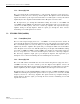

Table Of Contents
- ABOUT THIS MANUAL
- ADMONISHMENTS
- GENERAL SAFETY PRECAUTIONS
- FCC Compliance Statement
- STANDARDS CERTIFICATION
- LIST OF ACRONYMS AND ABBREVIATIONS
- SECTION 1: OVERVIEW
- SECTION 2: Installation
- SECTION 3: Graphical User Interface
- SECTION 4: GENERAL INFORMATION

ADCP-75-237 • Issue 1 • 8/2007 • Section 1: OVERVIEW
Page 1-3
© 2007, ADC Telecommunications, Inc.
2 FEATURES
2.1 LED Status
Five LEDs on the front display repeaters status. LED indicators are defined in Table 1-1.
Table 1-1.LED Indicators
COLOR STATUS
Red Tx Shut Down
Red Rx Shut Down
Yellow Sleep Mode
Red Isolation Check
Green DC Power
2.2 Automatic Level Control (ALC)
If the forward or reverse RF output power exceeds 13dBm, the system automatically controls
the output power to maintain power and protect the repeater.
2.3 Sleep Mode
Sleep Mode is activated when the reverse output RF power drops below –65dBm for more than
three minutes. The repeater returns to normal operation when the signal goes over –65dBm.
2.4 Isolation Check
Isolation check LED for the forward path and reverse path comes on after the Donor antenna is
set up and the power is turned on. Automatic Gain set up is available within the repeater for the
Path - Isolation.
2.5 Over Power Shut Down
If the RF output power exceeds the maximum for more than five seconds, the repeater
automatically shuts down. After five minutes, the repeater checks and monitors the RF Power, if
the RF output power is above the maximum, repeater remains shut down. If RF output power is
back to normal, the repeater comes back on.
2.6 Graphical User Interface (GUI)
The GUI control interface is used to change to Sleep Mode, select different bands A, B, C, D, E,
and F of the US PCS service. Other features of the BDU such as the On/Off controls of the
system can be accessed through the USB port provided. All control is set “Automatic” when
shipped, you can change the setting using the GUI control interface provided.