
User's Manual
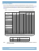
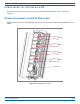
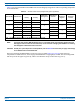
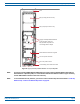


Table Of Contents

FlexWave
®
Prism Remote Unit and RF Module Installation Guide FWPP-504-02
Page 28 © May 2017 CommScope, Inc.
Configuring the System with RF
Table 17. Supported Bay Assignments and RF Antenna Labels for Legacy Dual-Bay 40W RF Modules
(From Top of Remote Unit Chassis Down)
Supported Bay Combinations for Legacy 40W Dual-Bay RF Modules RF Module
Cable,
RF Module
Connector, and
Remote Antenna
Connector Label
Function
Dual-Bay Tri-Bay Tri-Bay Quad-Bay
Bay D N/A N/A N/A
MOD D
MOD D
MOD C
Mod D TX0/RX0
Transmit RF power and
primary/Path 1 receive to/from
the antenna for RF Module D
Mod D TX1/RX1
Transmit RF power and
secondary/Path 2 receive
to/from the antenna for RF
Module D
Bay C N/A MOD C
MOD C
MOD C
Mod C TX0/RX0
Transmit RF power and
primary/Path 1 receive to/from
the antenna for RF Module C
Mod C TX1/RX1
Transmit RF power and
secondary/Path 2 receive
to/from the antenna for RF
Module C
Bay B
MOD B MOD B MOD B MOD B
MOD B
Mod B TX0/RX0
Transmit RF power and
primary/Path 1receive to/from
the antenna for RF Module B
Mod B TX1/RX1
Transmit RF power and
secondary/Path 2 receive
to/from the antenna for RF
Module B
Bay A MOD A MOD A
Mod A TX0/RX0
Transmit RF power and
primary/Path 1 receive to/from
the antenna for RF Module A
Mod A TX1/RX1
Transmit RF power and
secondary/Path 2 receive
to/from the antenna for RF
Module A
NOTE: For Dual Module installations, the center module shelf needs to be removed; see "Dual-Bay Modules Only—Remove the Module Bay
Shelf” on page 89.
NOTE: Install the Legacy Dual-Bay 40W RF Module in the lower-most bay in the chassis. If, however, if two Legacy Dual-Bay 40W RF Modules
are present, install the 2100 Module in the lower-most Bay and the 1900 Module in the upper-most Bay.