
User's Manual
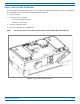
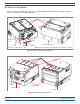
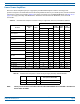
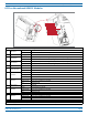
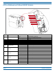
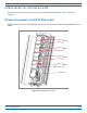
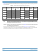
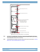
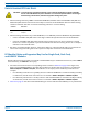
Table Of Contents

FlexWave
®
Prism Remote Unit and RF Module Installation Guide FWPP-504-02
Page 26 © May 2017 CommScope, Inc.
Configuring the System with RF
UNDERSTANDING RF CABLE RULES
• WheninstallingaDiversity,MIMOorDual-BandRFModule,bothRFcableslabeledMODNTX0/RX0and
MODNTX1/RX1shallbeconnectedtotheN-StyleconnectionsoftheRFModule.Notethatolderlabeling
schemesused“PRI”and“DIV”.Tomatcholdlabelingschemestocurrentlabeling:
• WheninstallingaNon-DiversityorSISORFModule,oranSMR800/900Dual-BandDual-BayRFModule:
– ConnecttheMODNTX0/RX0cabletothesingleavailableN-StyleRFConnectionoftheRFModule.
– ConstraintheMODNTX1/RX1cablewiththeexistingcablesusingatiewraporsimilarlyaccepted
fastenersoitcannotbepinchedorpreventtheRemoteUnitdoorfromclosing.Donotcutorattemptto
otherwiseremovethisRFCable.
• RFcablesarehand-malleable;however,cablesmustadheretoaminimumbendradiusof1-inchfromthe
outletoftheintegratedcableguidetotherespectiveN-StyleRFconnectionontheRFModule.
RF Module Cables and Supported Bay Use for Single-Card, Dual-Card,
and HDM RF Modules
TheRFcableandconnectorlabelscorrespondtotheRFModulebaysintheRemoteUnitchassis,whereMOD A
isthebottombayandMOD Disthetopbay.
• ThecablesandconnectorshavecorrespondinglabelsasshowninTable16onpage27forSingle-Card,
Dual-Card,andHDMRFModules.ForDual-Bayinstallations,theRFcablesandconnectorsarelabeledas
MOD N TX0/RX0andMOD N TX1/RX1,whereNreferstothetopbayofthedouble-bayinstallation.For
example:
– ForaDual-BayinstallationinaQuad-BaychassisinwhichtheRFModuleisinstalledintheBayDandBay
Ccombination,theRFcablesandconnectorsarelabeledasMOD D TX0/RX0andMOD D TX1/RX1.
– ForaDual-BayinstallationinaTri-BaychassisinwhichtheRFModuleisinstalledintheBayBandBay
Acombination,theRFcablesandconnectorsarelabeledasMOD B TX0/RX0andMOD B TX1/RX1.
• Table16onpage27alsoshowswhichRFModuletypecanbeinstalledinwhichPRUbayorbaycombination.
CAUTION! To avoid the risk of equipment damage, ensure that the AC/DC Power switch to the PRU
chassis and all RF Module DC power switches are in their OFF position before connecting or
disconnecting coaxial cables; otherwise equipment damage may occur.
Old Label New Label
PRI TX0/RX0
DIV TX1/RX1