
User's Manual
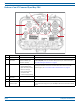
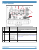
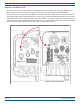
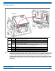
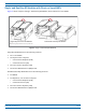
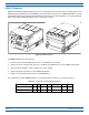
Table Of Contents

Overview of Prism Remote Units
FWPP-504-02 FlexWave
®
Prism Remote Unit and RF Module Installation Guide
© May 2017 CommScope, Inc. Page 9
DC-Powered Quad-Bay PRU
Ref # Component Device Function
1 DC Power port Pass-through gland Connection point between the PRU and a -40 to -60 Vdc power source.
2 Network Connector
port
RJ-45 female connector LAN Extension of the Host Unit Network that provides access to the Prism Network
for access and monitoring via an up to a 100 Mbps IP back-haul connection to
remote devices.
3 AUX connector Four contact closure inputs Connection points for two external alarm inputs.
4 Antenna connectors Eight Input/Output
Impedance 50Ω N-Type
connectors (female)
Connection points between the PRU and up to eight antennas that are labeled M
OD
X TXO/RXO or M
OD X TX1/RX1(where the first X can be A, B, C, or D). For further
information, see "Understanding RF Cable Rules” on page 26.
5 Fiber connectors One of the following:
• Hardened Multi-Fiber Optic
Connector (shown)
•Fiber Pass-Through
• ProAx connectors that
provide four BX5
connectors (Legacy PRUs)
Connection points between the PRU and the Outside Plant (OSP) box. For further
information on the three Fiber connector types, see "Connect Fiber Cable to the
PRU Chassis” on page 56.
6 Dual-Ground
connector
Ground connector Grounds the PRU.
POWER
48vdc/XXA
NETWORK
AUX
MOD A
TX1/RX1
MOD A
TXO/RXO
MOD B
TX1/RX1
MOD B
TXO/RXO
MOD C
TX1/RX1
MOD C
TXO/RXO
MOD D
TX1/RX1
MOD D
TXO/RXO
FIBER 1FIBER 2
123 4
5
6
CLASS 1
LASER PRODUCT