
User's Manual
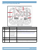
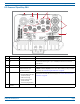
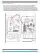
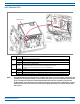
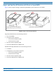
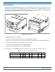
Table Of Contents

FlexWave
®
Prism Remote Unit and RF Module Installation Guide FWPP-504-02
Page 8 © May 2017 CommScope, Inc.
Overview of Prism Remote Units
Bottom of an AC-Powered Quad-Bay PRU
Ref # Component Device Function
1 AUX connector Four contact closure inputs Connection points for two external alarm inputs.
2 Antenna
connectors
Eight Input/Output
Impedance 50Ω N-Type
connectors (female)
Connection points between the PRU and antennas that are labeled M
OD X TXO/RXO
or M
OD X TX1/RX1(where the first X can be A, B, C, or D). For further information,
see "Understanding RF Cable Rules” on page 26.
3 Fiber connectors One of the following:
• Hardened Multi-Fiber
Optic Connector (shown)
•Fiber Pass-Through
• ProAx connectors that
provide four BX5
connectors (Legacy PRUs)
Connection points between the PRU and the Outside Plant (OSP) box. The Single-BAY
PRU only has the Fiber 1 connector. For further information on the three Fiber
connector types, see "Connect Fiber Cable to the PRU Chassis” on page 56.
4 Dual-Ground
connector
Ground connector Grounds the PRU.
5 AC Power port Sealed 3-pin port Connection point between the PRU and an AC power junction box.
6Network
Connector port
RJ-45 female connector LAN Extension of the Host Unit Network that provides access to the Prism Network
for access and monitoring via an up to a 100 Mbps IP back-haul connection to remote
devices.
2
5
1
3
4
6