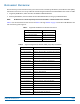
FlexWave® Prism Remote Unit and RF Module Installation Guide • FWPP-504-02 • May 2017 NETWORK NOKIA CDIU SeRF II CPRI PORT 1 CRAFT FAN REF NOKIA CDIU CPRI PORT 1 CRAFT REF PATH A OUT OUT CONFIG CPRI PORT 2 CPRI PORT 2 NOKIA CDIU CPRI PORT 1 CRAFT REF PATH A PATH B OUT DC POWER CONFIG PWR PWR CRAFT PATH A PATH B PATH B REV RF OUT PWR REV RF OUT PWR STATUS CONFIG FWD REF IN FWD NOT TO EXCEED +6 dBm PWR CPRI PORT 2 STATUS FWD REF IN FWD NOT TO EXCEED +6 dBm
DISCLAIMER This document has been developed by CommScope, and is intended for the use of its customers and customer support personnel. The information in this document is subject to change without notice. While every effort has been made to eliminate errors, CommScope disclaims liability for any difficulties arising from the interpretation of the information contained herein.
TABLE OF CONTENTS Document Overview...............................................................................................................................................................................................1 Document Revision History ........................................................................................................................................................................................3 Document Cautions and Notes ............................................
Table of Contents Connect the Power Wiring .......................................................................................................................................................................................76 Option 1: Connect the AC Power Wiring ..........................................................................................................................................................76 Option 2: Connect the DC Power Wiring...................................................
DOCUMENT OVERVIEW This document provides the information you need to install a CommScope FlexWave® Prism Remote Unit (PRU). Installation instructions are also provided for the following Prism Remote Unit RF Modules that reside in a PRU: • Single-Bay RF Modules, which includes the HDM and TDD RF Modules • Dual-Bay RF Modules, which includes the Dual-Band RF Modules and Legacy 40W RF Modules. NOTE: RF Modules are ordered separately and must be installed in a Prism Remote Unit in the field.
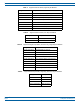
Document Overview Table 3. Supported Classic DART, Single Bay RF Modules Catalog Number Description FWP-I 2 1 00 0 0 M O D 6.5W 800 APAC, Non-Diversity, Classic (Extended 1 MHz) FWP-4210000M OD 6.
Document Overview Table 7. Supported Single SuperDARTs, Diversity, Single Bay RF Modules Table 8. Catalog Number Description FWP-6226000MOD 10W 900 EGSM FWP-K226000MOD 10W 900 P-GSM FWP-7426000MOD 20W 1800 GSM FWP-9426000MOD 20W 2100 UMTS FWP-A426000MOD 20W 2100 AWS FWP-8426000MOD 20W 1900 PCS Supported Dual Classic DART, Two Bay RF Modules Catalog Number Description FWP-D210000MOD 6.
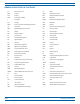
Document Overview ABBREVIATIONS USED IN THIS GUIDE AC Alternating Current M Meter AMP Amperes Mbps Megabits Per Second AUX Auxiliary MDI Medium Dependent Interface AWG American Wire Gauge MHz Megahertz C Centigrade MIMO Multiple-Input Multiple-Output CAT Category MM Millimeter CDRH Center for Diseases and Radiological Health MOD Module cm Centimeter MPE Maximum Permissible Exposure DART Digital/Analog Radio Transceiver NC Normally Closed dB Decibel NO Normally Open d
Overview of Prism Remote Units O V ER V I E W OF PRISM REMOTE UNITS FlexWave PRUs control RF emissions, interface with the FlexWave Prism Host Unit II and perform the optical to electrical conversion for transport to the antennas. The PRU is an environmentally-sealed unit designed for outdoor use that houses the electronic assemblies such as the Digital/Analog Radio Transceiver (DART) board and the Power Amplifier, and seals out dirt and moisture.
Overview of Prism Remote Units PRISM REMOTE UNIT COMPONENTS Figure 1 shows the main components of the PRU and its corresponding RF Modules. Fan Module RF Module slots HDM RF Module SeRF Module DC Power switches for RF Modules Main AC/DC Power switch for the chassis Cable connectors Figure 1. Prism Remote Unit Components FlexWave® Prism Remote Unit and RF Module Installation Guide Page 6 FWPP-504-02 © May 2017 CommScope, Inc.
Overview of Prism Remote Units PORTS AND CONNECTORS Make sure you refer to the section that describes the PRU deployed in your installation. "Bottom of an AC-Powered Quad-Bay PRU” on page 8 and "DC-Powered Quad-Bay PRU” on page 9 shows the differences between an AC-powered and a DC-powered PRU. The differences will be the same for Single-Bay, Dual-Bay, and Tri-Bay chassis.
Overview of Prism Remote Units Bottom of an AC-Powered Quad-Bay PRU 2 1 6 3 5 4 Ref # Component Device Function 1 AUX connector Four contact closure inputs Connection points for two external alarm inputs. 2 Antenna connectors Eight Input/Output Impedance 50Ω N-Type connectors (female) Connection points between the PRU and antennas that are labeled MOD X TXO/RXO or MOD X TX1/RX1 (where the first X can be A, B, C, or D). For further information, see "Understanding RF Cable Rules” on page 26.
Overview of Prism Remote Units DC-Powered Quad-Bay PRU 1 2 3 4 POWER 48vdc/XXA CLASS 1 LASER PRODUCT MOD A TX1/RX1 MOD C TXO/RXO MOD D TX1/RX1 MOD C TX1/RX1 MOD A TXO/RXO MOD B TXO/RXO MOD B TX1/RX1 MOD D TXO/RXO 5 FIBER 2 AUX FIBER 1 NETWORK 6 Ref # Component Device Function 1 DC Power port Pass-through gland Connection point between the PRU and a -40 to -60 Vdc power source.
Overview of Prism Remote Units Remote Unit Status LED This section illustrates the Status LED on a Quad-Bay PRU. The Status LED for the Single-Bay, Dual-Bay, and Tri-Bay PRUs is in the same location and functions the same as the Status LED for the Quad-Bay PRU. The Remote Unit has a single red Status LED that is located on the bottom of the chassis.
Overview of Prism Remote Units SeRF Module LEDs SeRF Module LED LED Color Description • POWER • • • STATUS • SYNTH ALARM NOTE: POWER STATUS SYNTH ALARM GREEN RED OFF GREEN • • • • Power OK and operating properly Power supply out of tolerance No power present No alarm for the SeRF II Module RED • Initial bootup sequence and should become GREEN within 1 minute; if RED after bootup, a Major alarm exists for the SeRF Module • GREEN • Locked • RED • Unlocked or is in initial bootup sequence • GREEN •
Overview of RF Modules for Prism Remote Units O V ER V I E W OF RF MODULES FOR PRISM REMOTE UNITS Dependent on the Prism Remote Unit model, a PRU enclosure can have from one to four RF Module bays and can support up to four RF Modules, as indicated by the model name. That is, the Single-Bay PRU has one RF Module bay and can only support one RF Module, and the Quad-Bay PRU has four RF Module bays and can support up to four RF Modules.
Overview of RF Modules for Prism Remote Units Prism supports the DART Module types listed below. • Classic DARTs are 6-timeslot DARTs that support up to 35 MHz contiguous bandwidth (see Table 9). • Single SuperDARTs are 6-timeslot DARTs that support two non-contiguous bands in the entire frequency range of the DART, but cannot exceed 35 MHz total RF bandwidth (see Table 10).
Overview of RF Modules for Prism Remote Units Table 11.
Overview of RF Modules for Prism Remote Units Single- and Dual-Bay RF Modules with Classic or SuperDARTs Figure 2 shows examples of Single- and Dual-Bay RF Modules, both of which have two DARTs. DART Card DART Card Single-Bay Dual-Card RF Module Dual-Band Dual-Bay RF Module NOTE: Some Single-Bay RF Modules have only 1 DART Card. Figure 2.
Overview of RF Modules for Prism Remote Units HDM RF Modules High-Density Module (HDM) RF Modules (Figure 3) are designed to provide the ability to deploy either a two 20W Multiple Input Multiple Output (MIMO) paths of the same band, known as a MIMO RF Module; two 20W Single Input Single Output (SISO) with two different bands, known as dual RF Module; or a single 40W Single Input Single Output (SISO) RF Module within a single-bay of a PRU. Figure 3.
Overview of RF Modules for Prism Remote Units Legacy Dual-Bay 40W RF Modules The Legacy Dual-Bay 40W RF Module (Figure 5) is designed for AWS and PCS frequencies and is supported only by Classic DARTs. The Legacy Dual-Bay 40W RF Module comprises: • one Classic DART • one Duplexer that comprises – one Low Noise Amplifier (LNA) – one Power Detector (PD) • two Power Amplifiers (PAs) • one Remote DART Interface (RDI) board.
Overview of RF Modules for Prism Remote Units RF MODULE COMPONENTS Figure 5 shows typical RF Module components, using the Single-Bay RF Module as an example, and Figure 6 shows the components of an HDM RF Module. DARTs Moun ng latch Moun ng LNA (inside the Duplexer cavi y) hook Power Amplifier (PA) Duplexer NOTE: The RDI is internal to the RF Module and is therefore not shown. Figure 5.
Overview of RF Modules for Prism Remote Units Linear Power Amplifiers The Linear Power Amplifier (LPA) is a high quality broadband RF amplifier used for achieving Prism product-rated power for the Remote Unit Tx forward path RF. The PAs are pass-band specific, with the maximum composite Tx power levels listed in Table 13 for Single-Card, Dual-Card, and HDM RF Modules and Table 14 on page 19 for Legacy Dual-Bay 40W RF Modules. The LPA is housed within the RF Module, and is not field serviceable. Table 13.
Overview of RF Modules for Prism Remote Units Duplexer and Low Noise Amplifier The RF Module provides the Remote Unit with an internal Duplexer that is optimized to provide the desired RF band-pass filtering and in-band equipment isolation between FWD and REV paths. The Duplexer provides the filtering necessary to the transmit and receive paths to and from the connected antenna.
Overview of RF Modules for Prism Remote Units LEDS on Narrowband HDM RF Modules 1 2 3 4 5 6 7 8 9 10 11 12 Ref # 1 DPM Power 2 FPGA Status 3 4 LVDS 0 Status LVDS 1 Status 5 DSP/GC Status 6 FPGA Load Status 7 8 9 10 11 12 1 LED TXA Status RXA Status TMA A Status TXB Status RXB Status TMA A Status LED Color Description Green HDM RF Module is powered on. Red Problem with the HDM RF Module power. Blinking Green Blinks as heartbeat of the HDM RF Module.
Overview of RF Modules for Prism Remote Units LEDS on Wideband and Fullband HDM RF Modules 1 2 3 4 5 6 7 8 9 10 Ref # LED LED Color Description Green HDM RF Module is powered on. Red Problem with the HDM RF Module power. 1 DPM Power 2 FPGA Status — Not used. 3 LVDS 0 Status — Not used. 4 LVDS 1 Status — Not used. 5 DSP/GC Status — Not used. 6 FPGA Load Status 7 TXA Status 8 9 10 RXA Status TXB Status RXB Status Red FPGA is in startup mode. Off FPGA load is complete.
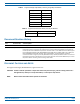
Configuring the System with RF CONFIGURING THE SYSTEM WITH RF The following sections describe how to correctly pair RF Modules with PRU slots, cables, and Antenna connectors. RF GROUP ASSIGNMENTS FOR PRU RF MODULE BAYS A PRU comprises from one to four RF Module bays. Figure 7 illustrates the numbering of RF Module bays and DARTs. Quad-Bay Remote Unit with Single-Card RF Modules DART 7 Bay D DART 8 DART 5 Bay C DART 6 DART 3 Bay B DART 4 DART 1 Bay A DART 2 SeRF Module Figure 7.
Configuring the System with RF Table 15 lists how the FlexWave Prism EMS references the RF group assignments and corresponding components of each RF Module. Table 15.
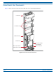
Configuring the System with RF Fans Bay D (empty for future use) Bay C (empty for future use) Legacy Dual-Bay 40W RF Module in Bay B (upper slot) and Bay A (lower slot) with the controlling DART in Bay B SeRF Module and Power supplies Four DC power switches AC or DC power switch Connec vity panel with Status LED Figure 8.
Configuring the System with RF UNDERSTANDING RF CABLE RULES CAUTION! To avoid the risk of equipment damage, ensure that the AC/DC Power switch to the PRU chassis and all RF Module DC power switches are in their OFF position before connecting or disconnecting coaxial cables; otherwise equipment damage may occur. • • • When installing a Diversity, MIMO or Dual-Band RF Module, both RF cables labeled MOD N TX0/RX0 and MOD N TX1/RX1 shall be connected to the N-Style connections of the RF Module.
Configuring the System with RF Table 16.
Configuring the System with RF Table 17.