
User's Manual
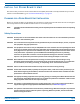


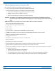
Table Of Contents
- Install the Prism Remote Unit
- Planning for a Prism Remote Unit Installation
- Unpack and Inspect the Prism Remote Unit and Components
- Mount the Prism Remote Unit
- Ground the PRU Chassis
- Connect a Network Cable to the PRU Chassis
- Connect Fiber Cable to the PRU Chassis
- Connect the Antenna Cable
- Determine the Circuit Breaker or Fuse for the PRU
- Connect the Power Wiring
- (Optional) Connect the Prism Remote Unit to a UPS

FlexWave
®
Prism Remote Unit and RF Module Installation Guide FWPP-504-02
Page 36 © May 2017 CommScope, Inc.
Install the Prism Remote Unit
Installation Tools and Supplies
ThetoolsandanyadditionalmaterialsrequiredforinstallandmountthePRUaredependentonthemounting
location.
Tools Required for All Mounting Methods
TheMountingBracketshipswiththePRU—itsecuresthePRUtoitspackingcrate.Allinstallationsrequireat
leastoneeachofthefollowing,whichmustbeprovidedbytheinstaller:
• tapemeasure
• pencil
orothermarkingdevice
• 3/8-inchFl
at-Bladescrewdriver
• lif
tingequipmentforPRU.
Additional Tools and Supplies Required for Steel-Pole Mounting
WhenmountingthePRUtoasteelpole,inadditiontothesupplieslistedin"ToolsRequiredforAllMounting
Methods”onpage36thefollowingsuppliesareneeded:
• onehammer,
>16-ounces
• oneStrapTensioning/Clampin
gTool(UlineModelNo.H-1273,orequivalent)
• Table20showsthenumberofstainless-steelstrapsandstainless-s
teelbucklesrequiredforeachPRUtype,
inwhichyoumusthavethesamenumberofbucklesasstraps.
– U
se1/2-inchto3/4-inch201,301,304or316Stainless-SteelStrappingwithaminimumtensilestrength
of1500pounds(UlineModelNo.S-11329,orequivalent).
– UseStainless-SteelB
ucklesdesignedspecificallyfortheabove-mentionedstrapping(UlineModelNo.
S-11331,orequivalent).
Table 20. Required Stainless-Steel Bands for Steel-Pole Mounting
CommScope Catalog Number Number of Bands Required for Installation
FP4-XXXXX0021XXRU - Quad-Bay Remote
4
FP3-XXXXX0021XXRU - Tri-Bay Remote
3
FP2-XXXXX0021XXRU - Dual-Bay Remote
FP1-XXXXX0021XXRU - Single-Bay Remote
2