
User's Manual
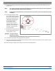
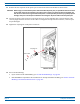
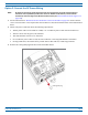
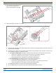
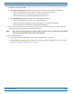
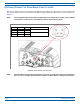
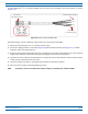
Table Of Contents
- Install the Prism Remote Unit
- Planning for a Prism Remote Unit Installation
- Unpack and Inspect the Prism Remote Unit and Components
- Mount the Prism Remote Unit
- Ground the PRU Chassis
- Connect a Network Cable to the PRU Chassis
- Connect Fiber Cable to the PRU Chassis
- Connect the Antenna Cable
- Determine the Circuit Breaker or Fuse for the PRU
- Connect the Power Wiring
- (Optional) Connect the Prism Remote Unit to a UPS

Install the Prism Remote Unit
FWPP-504-02 FlexWave
®
Prism Remote Unit and RF Module Installation Guide
© May 2017 CommScope, Inc. Page 83
A4-WireM8picofast
®
6-or10-meter26AWGcableisusedtoconnectthePRUtotheexternaldevice,asshown
inFigure18.
Figure 18. 4-Wire picofast 26
AWG Cable
DothefollowingtoconnectaUPStotheAUXConn
ectoronthebottomofthePRU:
1 Obt
aintherequiredlengthof6-or10-meterpicofastcable.
2 Orien
tthecouplingfasteneronthecable(Figure18)withtheAUXConnectorpins(Figure17),andthen
fastenthecabletotheAUXConnector.
3 Route
thecablefromthePRUAUXConnectortotheUPS(ifnotalreadyrouted)andthencuttotherequired
length.Allowsufficientslackfordressingandorganizingthecableattheexternaldevice.
4 S
tripbacktheoutercablesheathandinsulationtoexposethewiresattheendofthecableandstripback0.2
inches(5mm)ofinsulationfromeachwire.
5 Connectthealarmwirepairstoth
eappropriateterminalsontheexternaldevice.
6 Dressandsecurecableperstandardindustrypractice.
NOTE: If necessary, order a Prism AUX
4-wire cable assembly, CommScope part number 1451903.
Strip cable
0.2 inches (5 mm)
Connect 4 wires to UPS
Connect to
PRU AUX Connector
2
4
1
3