
User's Manual
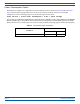
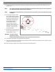
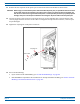
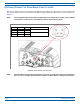
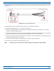
Table Of Contents
- Install the Prism Remote Unit
- Planning for a Prism Remote Unit Installation
- Unpack and Inspect the Prism Remote Unit and Components
- Mount the Prism Remote Unit
- Ground the PRU Chassis
- Connect a Network Cable to the PRU Chassis
- Connect Fiber Cable to the PRU Chassis
- Connect the Antenna Cable
- Determine the Circuit Breaker or Fuse for the PRU
- Connect the Power Wiring
- (Optional) Connect the Prism Remote Unit to a UPS

FlexWave
®
Prism Remote Unit and RF Module Installation Guide FWPP-504-02
Page 82 © May 2017 CommScope, Inc.
Install the Prism Remote Unit
(OPTIONAL) CONNECT THE PRISM REMOTE UNIT TO A UPS
Thefour-pinAUXConnectoronthebottomofthePRUallowsthePRUtobeconnectedtoanexternaldevicewith
drycontactconnections,suchasanUninterruptedPowerSupply(UPS).TheAUXConnectorpinsareshownin
Figure17.
NOTE: The Normally Open (NO) or Normally Closed (NC) options are
configurable in the GUI; see the “Manage
Contact Alarms” section of the current EMS System Setup and Provisioning Guide.
Figure 17. AUX Conn
ector Pin Orientation
NOTE: The Major/Minor setting of the AUX Connector pins cannot be
configured in the Prism 6.x EMS GUI. In
Prism 7.x, you can configure the Contact Alarm as Major or Minor (Alarms > Manage Contact Alarms).
1
2
4
3
AUX Connector
Boom of PRU
Pin # Contact Color Alarm Input
1 NO/NC Brown Major External Alarm Input
2 CO White
3 NO/NC Blue Minor External Alarm Input
4 CO Black