
User's Manual
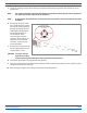
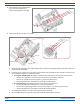
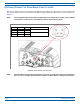
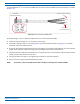
Table Of Contents
- Install the Prism Remote Unit
- Planning for a Prism Remote Unit Installation
- Unpack and Inspect the Prism Remote Unit and Components
- Mount the Prism Remote Unit
- Ground the PRU Chassis
- Connect a Network Cable to the PRU Chassis
- Connect Fiber Cable to the PRU Chassis
- Connect the Antenna Cable
- Determine the Circuit Breaker or Fuse for the PRU
- Connect the Power Wiring
- (Optional) Connect the Prism Remote Unit to a UPS

Install the Prism Remote Unit
FWPP-504-02 FlexWave
®
Prism Remote Unit and RF Module Installation Guide
© May 2017 CommScope, Inc. Page 81
6 ConnectthewirestothedesignatedterminalsontheDCPowerSourceDistributionPanel.Thefollowing
connectionsaretypicallymade:
• Inatypical-48Vdcplant,thehighestpotentialisthe0(groundorreturn)lead;youtherefore:
– connectthe0(groundorreturn)leadtothepositive(+)con
nector(redwire)
– connectthe-48Vdcleadto
thenegative(-)connector(blackwire)
– connectthethirdwire,ifprovided,to
theEarthGroundterminal.
• Ina+4
8Vdcplant,thehighestpotentialisthe+48lead;youtherefore:
– connectthe+48leadtothepositive(+)connecto
r(redwire)
– connectthe0potential(groundorreturn)tothenegative(-)co
nnector(blackwire)
– connectthethirdwire,ifprovided,to
theEarthGroundterminal.
7 Dressandsecurethewirestotherackfoll
owinglocalpractice.Routewiringawayfromsharpedgesand
secureinplacetopreventchaffingandprovidestrainrelief.
NOTE: Route all DC input wiring away from any sharp edges and properly
secure it in place to prevent chafing
and to provide strain relief. Lace the wires to the rack frame.
8 Dooneofth
efollowing:
• Ifyou
needtoinstallanRFModule,goto"InstalltheRFModule(s)”onpage84.
• Ifthe
RFModulesrequiredforthisinstallationarealreadyinstalledinthePRU,goto"PowerontheRF
Module(s)andthePrismRemoteUnit”onpage110.