
User's Manual
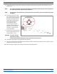
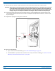
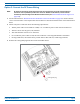
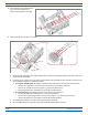
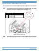
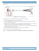
Table Of Contents
- Install the Prism Remote Unit
- Planning for a Prism Remote Unit Installation
- Unpack and Inspect the Prism Remote Unit and Components
- Mount the Prism Remote Unit
- Ground the PRU Chassis
- Connect a Network Cable to the PRU Chassis
- Connect Fiber Cable to the PRU Chassis
- Connect the Antenna Cable
- Determine the Circuit Breaker or Fuse for the PRU
- Connect the Power Wiring
- (Optional) Connect the Prism Remote Unit to a UPS

FlexWave
®
Prism Remote Unit and RF Module Installation Guide FWPP-504-02
Page 80 © May 2017 CommScope, Inc.
Install the Prism Remote Unit
4 Disconnecttheringterminalsfrom
thepower-terminalblock,as
showninthe
graphictotheright.
5 ConnecttheD
CpowercabletothePRU.
a Routethe
endoftheDCpowercablewiththethreeconductorsthroughtheopencable-glandconnector
onthebottomofthePRU.
b Crimpthethreeconductorstothepowerringterminal
s.Theterminalblockislabeledastowhereeach
wireshouldbeconnected,asdescribedbelow.
• Inatypical-48Vdcplant,thehighestpotentialisthe0(groundorreturn)lead;youtherefore:
– connectthe0(grou
ndorreturn)leadtothepositive(+)connector(redwire)
– connectthe-48Vdcleadtothenegative(-)connector(blackwire)
– connectthethirdwire,ifprovided,totheEarthGroundterminal.
• Ina+4
8Vdcplant,thehighestpotentialisthe+48lead;youtherefore:
– connectthe+48leadtoth
epositive(+)connector(redwire)
– connectthe0potential(groundorreturn)tothenegative(-)connector(blackwire)
– connectthethirdwire,ifprovided,totheEarthGroundterminal.
c UseaPhi
llipsscrewdrivertotorquetheringterminalsto18in-lbs.
d Use
a42MMwrenchtotorquethelargenutoutsidethecableglandto44in-lbs.
Posive (+)
Negave (-)
Earth ground
Posive (+)
Negave (-)
Earth ground
Step 4a
Steps 4b and 4c
Step 4d