
User's Manual
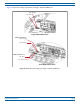
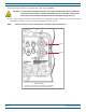
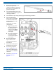
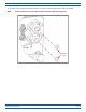
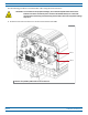
Table Of Contents
- Install the Prism Remote Unit
- Planning for a Prism Remote Unit Installation
- Unpack and Inspect the Prism Remote Unit and Components
- Mount the Prism Remote Unit
- Ground the PRU Chassis
- Connect a Network Cable to the PRU Chassis
- Connect Fiber Cable to the PRU Chassis
- Connect the Antenna Cable
- Determine the Circuit Breaker or Fuse for the PRU
- Connect the Power Wiring
- (Optional) Connect the Prism Remote Unit to a UPS

FlexWave
®
Prism Remote Unit and RF Module Installation Guide FWPP-504-02
Page 62 © May 2017 CommScope, Inc.
Install the Prism Remote Unit
Option B: Fiber Pass-Through Connector
NOTE: Use the following procedure to install the fiber cables using a Fiber Pass-Through Connector.
• If the PRU that you are installing has a Hardened Multi-Fiber Optic
Connector, follow the procedure
in "Option A: Hardened Multi-Fiber Optic Connector” on page 56
• If the PRU that you are installing has a legacy ProAx Connector,
follow the procedure in "Option C:
ProAx Connector (Legacy A
C-Powered PRUs)” on page 67.
NOTE: The graphic shown in this procedu
re depict an AC-powered PRU. However, the Fiber 1 and Fiber 2
connectors on a DC-powered PRU are in the same location and use the same procedure as the
AC-powered PRU to install fiber cables using a Fiber Pass-Through Connector.
Usethefollowingproceduretoinsta
llthefibercablesusingtheProAxconnector:
1 Ob
tainanenvironmentallyhardenedfibercableterminatedwithLCconnectors.Theoutsidediameterofthe
cablejacketmustbebetween.035and.63inches.
2 Complete
theinstallationstepsin"UnpackandInspectthePrismRemoteUnitandComponents”onpage39
through"ConnectaNetworkCabletoth
ePRUChassis”onpage54.
CAUTION! To avoid the risk of equipment damage, ensure that the AC/DC Power switch to the Remote
Unit chassis and the DC power switch to all RF Module bays are in their OFF position before
connecting or disconnecting coaxial cables; otherwise equipment damage may occur.