
User's Manual
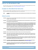


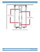
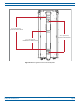
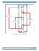
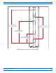
Table Of Contents
- Install the Prism Remote Unit
- Planning for a Prism Remote Unit Installation
- Unpack and Inspect the Prism Remote Unit and Components
- Mount the Prism Remote Unit
- Ground the PRU Chassis
- Connect a Network Cable to the PRU Chassis
- Connect Fiber Cable to the PRU Chassis
- Connect the Antenna Cable
- Determine the Circuit Breaker or Fuse for the PRU
- Connect the Power Wiring
- (Optional) Connect the Prism Remote Unit to a UPS

FlexWave
®
Prism Remote Unit and RF Module Installation Guide FWPP-504-02
Page 30 © May 2017 CommScope, Inc.
Install the Prism Remote Unit
CAUTION! Always allow sufficient fiber length to permit routing of patch cords and pigtails without severe bends.
Fiber optic patch cords or pigtails may be permanently damaged if bent or curved to a radius of less than
2 inches (5.1 cm).
CAUTION! Always use an Electro-Static Discharge (ESD) wrist strap whenever you work with the Prism Remote Unit
or its components. Make sure that it maintains maximum contact with bare skin. ESD grounding straps
are available with banana plugs, metal spring clips, or alligator clips. To ensure adequate grounding,
connect the ESD wrist strap to any bare metal surface of the Prism Remote Unit chassis (which may
require that you scrape off some of its protective coating), or to the Dual-Ground Connector at the
bottom of the unit. For information on the Dual-Ground Connector, see "Ports and Connectors” on
page 7.
CAUTION! Service personnel must confirm that the perimeter gasket and door-to-door gaskets are in place when
closing the Remote Unit doors after servicing.
Mounting Plans
ThePRUhasalow-profiledesignthatrequiresminimalrealestateforinstallation.Thebasicdimensionsand
weightsofthePRUarelistedinTable19onpage31andTable18onpage31.
ThePRUshouldbemountedonautilitypole,mast,oronaflats
urface.AMountingBracketshipswitheach
Remote.Installationconsistsofsecuringthebrackettothemountingsurface(wood,concrete,orsteel)andthen
hangingtheunitfromthebracket.thePRUshouldonlybemountedinarestrictedaccesslocation.
BeforemountingthePRU,makesurethatthefollowingrequirementsaremet.
• The
PRUmust
– be
installedonlyinarestricted-accesslocation
– m
ustbelocatedasspecifiedinthesystemdesignplan(notdocumentedhere).Ifasystemdesignplanhas
notbeenprepared,consultwiththeTechnicalSupportforWirelessProductsteamforassistance(see
"DCCSGlobalTechnicalSupport”onpage124).
– musthaver
eadyaccesstothespecifiedACorDCpowersource.
• Ifyoumoun
tthePRUinahorizontalposition,youmustmountitataslightangle,withthetopofthePRU
chassisangledhigherthanthebottom,whichcreatesaslopethatallowswaterorsnowtorunoffthePRU
chassis.Ifitismountedindoors,nosloperequired.
• If
youmountthePRUinanupside-downhorizontalposition(i.e.,aceilingmount),attachsafetyleashesthat
cansupporttheweightofafullypopulatedchassis(seeTable18onpage31).
• Thesitechosenmust
– confo
rmtoalllocalcodes;requiredpermitsmustbeobtainedpriortomountingaPRU
– complywiththeunitenvironmentalspecifications
– be
opentofreeairspaceonthebottom(cableentryend),thetop,thefront,andbothsides
– allow
adequateclearanceatthebottomofthePRUtoprovideaccessforattachingcablesandforviewing
theLEDindicator
– pro
vide18inches(45.7cm)ofclearanceonthefrontandbothsidesofthePRUtoallowdoorstobe
openedforserviceandtoallowfreeaircirculation
– canb
earthesizeandweightofthePRUenclosure,seeTable18onpage31andTable19onpage31