Install the Prism Remote Unit INSTALL THE PRISM REMOTE UNIT This section tells you how to install a Prism Remote Unit (PRU). If the PRU is already installed and you need to add one or more RF Modules, go to "Install the RF Module(s)” on page 84. PLANNING FOR A PRISM REMOTE UNIT INSTALLATION Before you unpack the PRU, you should first plan for where it will be mounted and collect the tools and supplies that are required to mount the PRU and then connect it to a Prism system.
Install the Prism Remote Unit CAUTION! Always allow sufficient fiber length to permit routing of patch cords and pigtails without severe bends. Fiber optic patch cords or pigtails may be permanently damaged if bent or curved to a radius of less than 2 inches (5.1 cm). CAUTION! Always use an Electro-Static Discharge (ESD) wrist strap whenever you work with the Prism Remote Unit or its components. Make sure that it maintains maximum contact with bare skin.
Install the Prism Remote Unit Table 18. Prism Remote Unit Weights (1) PRU Model Unpopulated Populated Single-Bay Pounds 65 Kilograms 29 83 38 Pounds 81 Kilograms 37 117 53 Pounds 97 Kilograms 44 151 68 Pounds 116 Kilograms 53 188 85 Dual-Bay Tri-Bay Quad-Bay 1 Unpopulated” weight includes the SeRF Module and the Solar shields, which are always present. “Populated” weight is the weight of the chassis that has the SeRF Module and RF Modules installed. Table 19.
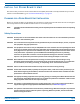
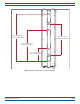
Install the Prism Remote Unit 14.5” (36.83 cm) Top Band to Bo om Band 14.0” (35.56 cm) Top Bolt to Bo om Bolt Figure 9. Mounting Dimensions for Single-Bay PRUs FlexWave® Prism Remote Unit and RF Module Installation Guide Page 32 FWPP-504-02 © May 2017 CommScope, Inc.
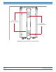
Install the Prism Remote Unit 21.7” (55.118 cm) Top Band to Bo om Band 21.0” (53.34 cm) Top Bolt to Bo om Bolt 12.1” (30.734 cm) MiddleBand to Bo om Band Figure 10. Mounting Dimensions for Dual-Bay PRUs FWPP-504-02 © May 2017 CommScope, Inc.
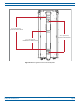
Install the Prism Remote Unit 30.6” (77.724 cm) Top Band to Bo om Band 17.5 (44.45 cm) Top Bolt to Bo om Bolt 16.1” (40.894 cm) MiddleBand to Bo om Band Figure 11. Mounting Dimensions for Tri-Bay PRUs FlexWave® Prism Remote Unit and RF Module Installation Guide Page 34 FWPP-504-02 © May 2017 CommScope, Inc.
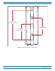
Install the Prism Remote Unit 41.7” (105.918 cm) Band 1 to Bo om Band 28.0” (71.12 cm) Top Bolt to Bo om Bolt 27.6” (70.104 cm) Band 2 to Bo om Band 11.1” (28.194 cm) Band 3 to Bo om Band Figure 12. Mounting Dimensions for Quad-Bay PRUs FWPP-504-02 © May 2017 CommScope, Inc.
Install the Prism Remote Unit Installation Tools and Supplies The tools and any additional materials required for install and mount the PRU are dependent on the mounting location. Tools Required for All Mounting Methods The Mounting Bracket ships with the PRU—it secures the PRU to its packing crate.
Install the Prism Remote Unit Additional Tools and Supplies Required for Wood-Pole Mounting When mounting the PRU to a wood pole, in addition to the supplies listed in "Tools Required for All Mounting Methods” on page 36, the following supplies are needed: • one electric drill, 1/2-inch or larger • one 1/2-inch drill bit • two 1/2-inch square-head through-bolt or equivalent that is long enough to extend through the utility pole • two 1/2-inch square nut or equivalent • two 1/2-inch square washer
Install the Prism Remote Unit Tools and Supplies Required to Connect a PRU The installation hardware provided with a PRU is listed below. • One 15-foot (4.
Install the Prism Remote Unit UNPACK AND INSPECT THE PRISM REMOTE UNIT AND COMPONENTS 1 Inspect the exterior of the shipping container(s) for evidence of rough handling that may have damaged the components in the container. 2 Check the contents for damage and verify with the packing slip. If damage is found or parts are missing, file a claim with the commercial carrier and notify CommScope Customer Service (see "DCCS Global Technical Support” on page 124).
Install the Prism Remote Unit c Loosen the two captive screws at the bottom of the PRU. Bo om of the PRU Cap ve screws on the PRU FlexWave® Prism Remote Unit and RF Module Installation Guide Page 40 FWPP-504-02 © May 2017 CommScope, Inc.
Install the Prism Remote Unit d e Hoist the PRU to an upright position and tap the crate downwards to separate the PRU from the Mounting Bracket. Hoist should be connected to the two D-Rings on the top of the PRU chassis Remove the Mounting Bracket from the crate: i Unscrew two bolts and remove the Mounting Bracket from the crate. ii Save the Mounting Bracket for field installation.
Install the Prism Remote Unit MOUNT THE PRISM REMOTE UNIT The PRU may be attached to a utility pole, a mast, or on a solid flat surface. Installation consists of securing the bracket to the mounting surface and then hanging the PRU from the bracket. The bracket may be attached to a variety of surfaces such as wood, concrete, or steel. This guide provides the information you need to install and use the FlexWave Prism Remote Mounting Kit.
Install the Prism Remote Unit Steel Pole Installation Using Steel Banding CAUTION! Always wear safety goggles when working with metal banding and when using tensioning tools. CAUTION! This section describes how to secure a PRU to a steel pole using steel bands. In high earthquake risk areas, CommScope advises in addition to banding, bolts should be used redundantly to ensure mechanical mounting capable of surviving severe seismic activity.
Install the Prism Remote Unit 3 Slide a buckle on the band and secure by doubling over under buckle, as shown in the illustration below, or as instructed in manufacturer's instructions. Bands should pass through each slot of the Mounting Bracket, from top to bottom, ensuring the band passes over the top of the pins, as shown below, and again through the buckle. 4 Wrap the band around pole once more, passing through the slots in the Mounting Bracket and over pins, and again through buckle.
Install the Prism Remote Unit 8 Clinch band stub in place by hammering down buckle ears, as shown below. 9 Repeat Step 3 on page 44 through Step 8 for each remaining banding slot of the Mounting Bracket. 10 Hang the PRU from the Mounting Bracket as shown in "Installing a PRU on the Mounting Bracket” on page 51. FWPP-504-02 © May 2017 CommScope, Inc.
Install the Prism Remote Unit Pole Mount Installation Using Bolts CAUTION! This section describes how to secure a PRU to a wood pole using bolts. In high earthquake risk areas, CommScope advises in addition to bolting, banding should be used redundantly to ensure mechanical mounting capable of surviving severe seismic activity. Typical areas where this attachment method are suggested are Earthquake Risk Zone 4, per Bellcore GR-63-CORE, section 4.4.1.1.
Install the Prism Remote Unit Wood-Framed Wall Mounting Procedure 1 Refer to "Mounting Cautions” on page 42 before beginning this process. 2 Locate the Mounting Bracket provided with the PRU Mounting Kit. 3 Obtain the tools and supplies listed in "Tools Required for All Mounting Methods” on page 36 and "Additional Tools and Supplies Required for Flat-Surface Mounting” on page 37. 4 Obtain plywood with a minimum thickness of 0.75-inches (19.0 cm) to be used as a backer board.
Install the Prism Remote Unit 9 Refer to the following figure and do the following: a From the side of the backer that will face the wall, drive a 1/2-inch Tee Nut into each drilled hole. b Mount the plywood backer on the wall and firmly secure it to the wall’s interior studs. c Locate the two 1/2 x 1-inch hex bolts and place a 1/2-inch lock washer and 1/2–inch flat washer on each bolt and then secure the Mounting Bracket to the plywood backer using the assembled bolts and washers.
Install the Prism Remote Unit Masonry Wall Mounting 1 Refer to "Mounting Cautions” on page 42 before beginning this process. 2 Locate the Mounting Bracket provided with the PRU Mounting Kit. 3 Obtain the tools and supplies listed in "Tools Required for All Mounting Methods” on page 36 and "Additional Tools and Supplies Required for Flat-Surface Mounting” on page 37. 4 Verify that concrete anchors to be used are designed for 1/2-inch bolts. 5 Hold the Mounting Bracket in position on the wall.
Install the Prism Remote Unit 7 Refer to anchor manufacturer's technical data to ensure proper drill diameter to be used, and then drill holes in the wall at the locations marked in Step 6. 8 Refer to the following figure and do the following: a Set the anchors in the wall. b Locate the two 1/2 x 1-1/2-inch mounting bolts and place a 1/2-inch lock washer and 1/2-inch flat washer on each bolt. c Place the Mounting Bracket over the two anchors.
Install the Prism Remote Unit Installing a PRU on the Mounting Bracket The basic procedure to hang a PRU on a Mounting Bracket is the same. The illustrations in this procedure, however, show a pole-mount installation. 1 Refer to "Mounting Cautions” on page 42 before beginning this process. 2 Use the D-Rings on the top of the PRU to hoist the PRU into position for attachment to the Mounting Bracket. CAUTION! To avoid damage to the PRU and to avoid personal injury, use appropriate lifting equipment.
Install the Prism Remote Unit GROUND THE PRU CHASSIS CAUTION! Avoid sharp bends in the ground wire. CAUTION! For proper and safe equipment operation, use a #6 copper wire terminated with the provided ring terminal to link the PRU to an earth-ground source. 1 Ensure that the AC/DC Power switch to the PRU chassis and the DC power switch to all RF Module bays are in their OFF position.
Install the Prism Remote Unit 2 Locate a #6 AWG (4 mm) copper grounding wire long enough to reach an approved earth ground. 3 Use a socket wrench with a 3/8-inch deep socket to remove the two 10-32 Keps Nuts from the Dual-Ground connector on the bottom of the PRU. 4 Secure the ring terminal end of the grounding wire to the ground studs on the unit using the two 10-32 Keps Nuts removed in Step 3, and then torque the nuts to 18 in-lbs ± 1 in-lb.
Install the Prism Remote Unit CONNECT A NETWORK CABLE TO THE PRU CHASSIS The PRU provides a Network port that allows communications with the internal processor and access to the Host LAN network. That is, this provides a LAN extension to the Host network. The Network port is 10/100/1000 BASE-T/TX (802.3ab compliant) MDI and requires a minimum of CAT 5 cable. NOTE: Although the interface might provide GigE, only 100 Mbps is provided for bandwidth between the Host and Remote.
Install the Prism Remote Unit 2 Route the network cable from the network connection to the underside of the PRU. 3 Align the plug end of the RJ-45 cable connector with the RJ-45 port receptacle and then insert the cable plug into the port receptacle. AC-Powered PRU DC-Powered PRU 4 Slide the connector nut up to the port until it engages the connector locking mechanism.
Install the Prism Remote Unit CONNECT FIBER CABLE TO THE PRU CHASSIS There are three fiber connector options for the Prism Remote Unit; follow the fiber cable installation process that is appropriate for the configuration of the PRU that you are installing: • "Option A: Hardened Multi-Fiber Optic Connector” on page 56 • "Option B: Fiber Pass-Through Connector” on page 62 • "Option C: ProAx Connector (Legacy AC-Powered PRUs)” on page 67.
Install the Prism Remote Unit Table 21 identifies how the fibers in the Multi-Fiber Optic Cable correlate to the SeRF SFPs, which come pre-wired from the factory. Table 21.
Install the Prism Remote Unit Figure 13 illustrates how the Multi-Fiber Optic Cables used with HMFOC connectors run between the Fiber 1 and Fiber 2 connectors and the SFPs. Fiber 1 assembly Fiber 2 assembly Fiber-op c cable runs between the Fiber 1 and Fiber 2 Connectors and the SFPs Fiber 1 and Fiber 2 cable Fiber 1 and Fiber 2 Connectors (bo om of PRU) Fiber 1 Connector (bo om of PRU) Figure 13.
Install the Prism Remote Unit Figure 14 shows the cabling requirements for Single- and Dual-WDM units. 1 RX - Orange 1 TX - Blue Single-WDM HMFOC Units WDM 1 Connector 1 1 RX - Orange 2 RX - Brown WDM 2 Connector 1 1 TX - Blue 2 TX - Green Dual-WDM HMFOC Units Figure 14. Multi-Fiber Optic Cabling for Single- and Dual- WDM Units FWPP-504-02 © May 2017 CommScope, Inc.
Install the Prism Remote Unit Use the following procedure to install the fiber cables using the HMFOC. CAUTION! To avoid the risk of equipment damage, ensure that the AC/DC Power switch to the Remote Unit chassis and the DC power switch to all RF Module bays are in their OFF position before connecting or disconnecting coaxial cables; otherwise equipment damage may occur. 1 Use a 7/16” wrench or socket to remove the dust-cover cap from the Fiber 1 connector, located at the bottom of the PRU.
Install the Prism Remote Unit 2 Rotate the coupling nut of the Multi-Fiber Optic cable counter-clockwise to remove its dust-cover cap, as shown in the graphic to the right. 3 Clean the Multi-Fiber Optic cable connector using industry approved cleaning procedures. 4 Clean the Fiber 1 port using industry approved cleaning procedure. 5 Insert the Multi-Fiber Optic cable into the FIBER 1 connector; refer to the introductory material for this section for information on cabling requirements.
Install the Prism Remote Unit Option B: Fiber Pass-Through Connector NOTE: NOTE: Use the following procedure to install the fiber cables using a Fiber Pass-Through Connector. • If the PRU that you are installing has a Hardened Multi-Fiber Optic Connector, follow the procedure in "Option A: Hardened Multi-Fiber Optic Connector” on page 56 • If the PRU that you are installing has a legacy ProAx Connector, follow the procedure in "Option C: ProAx Connector (Legacy AC-Powered PRUs)” on page 67.
Install the Prism Remote Unit 3 Remove connector plug only from the Fiber 1 connector, unless multiple fiber cables are needed. NOTE: Do not remove the dust cover from the Fiber 2 connector until directed to do so. Connector plugs FWPP-504-02 © May 2017 CommScope, Inc.
Install the Prism Remote Unit Insert the Fiber Optic cable, terminated with LC connectors, through the Fiber 1 Connector. FIBER 2 FIBER 1 4 Fiber 1 and Fiber 2 are Fiber Pass-Through Connectors AC or DC PRU (The Fiber 1 and Fiber 2 connectors are in the same loca on for both the AC- and DC-powered PRUs.) 5 Clean all LC connectors following industry approved procedure.
Install the Prism Remote Unit LC connectors plug into the SFP Figure 15. Connect LC Connector to SFP—Standard Configuration Connect a single LC connector to the WDM adapter WDM bracket and adapter Figure 16. Connect LC Connector to SFP—WDM Pass-Through Configuration FWPP-504-02 © May 2017 CommScope, Inc.
Install the Prism Remote Unit 7 Attach the strength member from the Fiber Optic cable to the Strain-Relief lug on the inside bottom of the PRU. Strain-relief lug 8 Tighten the external dome nut of the Pass-Through Connector around the Fiber Optic cable—torque the dome nut to 44 in-lbs plus or minus 4 in-lbs. 9 Route the fiber cable from the underside of the PRU to the OSP box. 10 Follow local practices to secure the fiber cable in place.
Install the Prism Remote Unit Option C: ProAx Connector (Legacy AC-Powered PRUs) NOTE: Use the following procedure to install the fiber cables using a legacy ProAx Connector. • If the PRU that you are installing has a Hardened Multi-Fiber Optic Connector, follow the procedure in "Option A: Hardened Multi-Fiber Optic Connector” on page 56 • If the PRU that you are installing has a Fiber Pass-Through Connector, follow the procedure in "Option B: Fiber Pass-Through Connector” on page 62.
Install the Prism Remote Unit Use the following procedure to install the fiber cables using the ProAx connector: CAUTION! To avoid the risk of equipment damage, ensure that the AC/DC Power switch to the Remote Unit chassis and the DC power switch to all RF Module bays are in their OFF position before connecting or disconnecting coaxial cables; otherwise equipment damage may occur. 1 Remove ProAx connector dust cover located at the bottom of the PRU.
Install the Prism Remote Unit 2 Remove the dust cap from the fiber cable BX5 connector (FIBER 1). 3 Clean all fiber connectors following industry approved procedure. 4 Align the plug end of the BX5 cable connector with the BX5 port receptacle and then insert the cable plug into the port receptacle as shown below, and then slide the strain relief boot over the connector.
Install the Prism Remote Unit 5 Route the fiber cable from the underside of the PRU to the OSP box. Observe the fiber numbers and their positions in the quad cable connector as shown below. The fibers at the other end of the fiber cable are numbered with the same numbering scheme. SFP1 FWD Fiber 1 REV Fiber 2 SFP1 SFP2 REV Fiber 4 FWD Fiber 3 SFP2 SFP3 FWD Fiber 1 REV Fiber 2 SFP3 SFP4 REV Fiber 4 FWD Fiber 3 SFP4 6 Secure fiber cable in place following local practices.
Install the Prism Remote Unit CONNECT THE ANTENNA CABLE Coaxial antenna cables must be routed from the antenna to the PRU. The cables must be terminated with an N-Type male connector for connection to the PRU antenna port or the lightning surge suppressor (accessory, required anytime the antenna is mounted in an area in which the antenna is susceptible to a lightning strike). CAUTION! The antenna(s) used for this transmitter must be fixed-mounted on (outdoor/indoor) permanent structures.
Install the Prism Remote Unit 3 Connect a lightning surge suppressor to the antenna port; torque to 8 ±1 in-lbs to ensure full connection. NOTE: The lightning surge suppressor is included in the RF Module’s shipping container. Lightning surge suppressor(s) are required anytime the antenna is mounted in an area in which the antenna is susceptible to a lightning strike.
Install the Prism Remote Unit Power Consumption 1 2 Calculate the maximum power consumption, which determines the circuit breaker or fuse to use. a Review the PRU order to determine the number of DARTs, number of power supplies, and the number of SFPs. Use this information to find the power consumption from Table 22 and Table 23 on page 75. b Enter the power consumption in the spaces provided below. c Add the Watts and enter the total in the Total Power Consumption field.
Install the Prism Remote Unit Power Consumption Tables The PRU power supplies are > 80% efficient, both AC and DC versions. The data in Table 22 and Table 23 on page 75 and the power-supply efficiencies can be used to estimate the input current for a given PRU configuration. Use the following equation to calculate the input current draw: Input Current = (Total Power Consumption / 0.
Install the Prism Remote Unit Table 23.
Install the Prism Remote Unit CONNECT THE POWER WIRING The PRU supports both AC and DC power. Follow the steps appropriate to your system configuration: • "Option 1: Connect the AC Power Wiring” on page 76 • "Option 2: Connect the DC Power Wiring” on page 79. Option 1: Connect the AC Power Wiring A 15-foot, 3-wire cable with connectors is provided for the AC power connections. The connector end of the cable connects to the AC power port located on the bottom of the unit.
Install the Prism Remote Unit 5 Install any AC power supply wires that may be required between the AC junction box and the AC circuit breaker box. NOTE: It is recommended that an AC outlet be installed near the PRU for powering tools and test equipment. This outlet must include a GFCI device for protection. NOTE: An appropriate disconnect device, as well as branch circuit protection, must be provided as part of the installation. 6 7 Connect the AC power cable wires to the AC power supply wires.
Install the Prism Remote Unit 11 Remove the dust cap from the AC power port located on the bottom of the PRU as shown below. CAUTION! While trying to connect the AC power cable to the PRU AC power port, it is possible for the line terminal on the cable connector to contact the ground pin on the power port. If the AC cable is energized, this will result in a direct short to ground for the AC power.
Install the Prism Remote Unit Option 2: Connect the DC Power Wiring NOTE: All electrical work must comply with local codes and requirements. A locally licensed electrical contractor is best qualified to perform this work. For additional information, consult with the CommScope Technical Support for Wireless Products team (see "DCCS Global Technical Support” on page 124).
Install the Prism Remote Unit 4 5 Disconnect the ring terminals from the power-terminal block, as shown in the graphic to the right. (+) ) ve Posi ga ve ( und Ne th gro Ear Connect the DC power cable to the PRU. +) ) e( (v si a ve und o P eg gro N rth a E Step 4d Steps 4b and 4c Step 4a a Route the end of the DC power cable with the three conductors through the open cable-gland connector on the bottom of the PRU. b Crimp the three conductors to the power ring terminals.
Install the Prism Remote Unit 6 Connect the wires to the designated terminals on the DC Power Source Distribution Panel. The following connections are typically made: • • 7 – connect the 0 (ground or return) lead to the positive (+) connector (red wire) – connect the -48 Vdc lead to the negative (-) connector (black wire) – connect the third wire, if provided, to the Earth Ground terminal.
Install the Prism Remote Unit (OPTIONAL) CONNECT THE PRISM REMOTE UNIT TO A UPS The four-pin AUX Connector on the bottom of the PRU allows the PRU to be connected to an external device with dry contact connections, such as an Uninterrupted Power Supply (UPS). The AUX Connector pins are shown in Figure 17. NOTE: The Normally Open (NO) or Normally Closed (NC) options are configurable in the GUI; see the “Manage Contact Alarms” section of the current EMS System Setup and Provisioning Guide.
Install the Prism Remote Unit A 4-Wire M8 picofast® 6- or 10-meter 26 AWG cable is used to connect the PRU to the external device, as shown in Figure 18. Connect to PRU AUX Connector 1 2 Connect 4 wires to UPS 3 Strip cable 0.2 inches (5 mm) 4 Figure 18. 4-Wire picofast 26 AWG Cable Do the following to connect a UPS to the AUX Connector on the bottom of the PRU: 1 Obtain the required length of 6- or 10-meter picofast cable.