
User Manual Part 2

Install the Remote
FlexWave Prism Host, Remote and EMS 5.1 System Reference Page 99
ADCP-77-073 • Issue 2 • 11/2009 © 2009 ADC Telecommunications, Inc.
In the following steps, the RF cables and connectors are referred to as
MOD
N
TX0/RX0
and as
MOD
N
TRX1
where
N
equals
A
,
B
,
C
, or
D
.
55 Unpack and inspect the RF Module as described in “Unpack and Inspect the
Remote and Components” on page 97.
66 Open the Remote enclosure.
77 Remove release liners, if present, from the thermal pads on the RF Module prior
to installing the module into the Remote chassis.
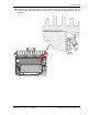
Thermal pads are located as follows:
•• one large pad on the back surface (LPA)
•• up to two on the front surface (DARTs)
•• two on the left side for the (RDI).
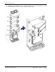
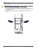
88 Hold the RF Module so that the DART card(s) face away from the Remote and the
Mounting Hook is toward the Receiving flange on the Remote chassis.
Handle the RF Module with care during installation. Be especially careful to not damage
the thermal- i
nterface material (TIM), which is attached to the LPA. If the TIM is damaged,
the LPA can overheat. B
efore installing the RF Module, check to see if the heatsink
material is gouged or cracked. If the TI
M is damaged, do not install the RF Module and
contact ADC for assistance (see “Contacting ADC” on page 335 for contact informat
ion).
If the thermal- interface material is damaged, the installation and use of the RF Module
may void the
warranty of the RF Module.
The thermal pads are very sensitive to mishandling—do not nick, scratch, or ding them.
Always install RF Modules from the bottom up and do not skip a shelf.