
User Manual Part 2

Initial Prism System Setup
Page 160 FlexWave Prism Host, Remote and EMS 5.1 System Reference
© 2009 ADC Telecommunications, Inc ADCP-77-073 • Issue 2 • 11/2009
When a Host DART is linked to a Remote DART in a multi-fibers configuration, the
EMS uses the first fiber (in numerical order) on which the required number of
timeslots is available for the passband being linked. The EMS will not divide up the
timeslots between two fibers. So, for example, if the passband requires eight
timeslots, and only six timeslots are available on the first fiber, the EMS will bypass
the first fiber and assign all eight timeslots to the second fiber, leaving four timeslots
unused on the second fiber.
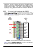
6.9.2 RF Groups in the Remote and the EMS GUI
The EMS
Alarm Summary of RF Groups
view displays up to four rectangles labeled
RF
Module / Band N
(where
N
equals
A
,
B
,
C
, or
D)
. Each rectangle represents one RF Module
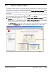
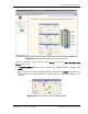
in the Remote. Figure 6-1 shows how the FlexWave EMS maps the RF Modules in the
GUI to the physical modules and antennas.
Figure 6-1. Matching Remote RF Modules to EMS Group Labels
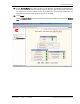
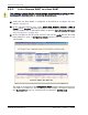
Figure 6-2 shows the
Alarm Summary of RF Groups
view. If a slot is not occupied by an
RF Module, the slot is shown with a white indicator.
MOD A
MOD B
MOD C
MOD D
Remote
RF Module
shelf labels
EMS
RF Module
labels