
User Manual Part 2
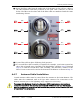
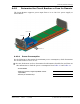
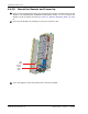

Install any 40W RF Module(s)
FlexWave Prism Host, Remote and EMS 5.1 System Reference Page 127
ADCP-77-073 • Issue 2 • 11/2009 © 2009 ADC Telecommunications, Inc.
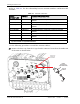
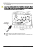
399 Connect the AC power cable wires to the AC power supply wires. Refer to the
following graphic to identify the color code and wire designations.
400 At the AC box, connect the AC power supply load wires to a circuit breaker or fuse.
411 Connect the ground wire to an approved earth ground.
422 Place the circuit breaker in the ON position and then test the connector end of the
AC power cable for proper voltage levels and correct polarity.
433 When testing is complete, place the circuit breaker in the OFF position.
For proper and safe equipment operation, an approved earth ground connection must
be provided and mai
ntained.
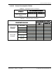
AC power cord
provided with Remote
Black
Green/Yellow
White
Line
Ground
Neutral
120 VAC power
wiring
120 VAC CONNECTIONS
Black
Green/Yellow
White
Line 1
Ground
Line 2
240 VAC power
wiring
240 VAC CONNECTIONS
77073-072
Connector Pin Designations
Pin 1 - Green/Yellow
Pin 2 - White
Pin 3 - Black
End view of
connector
1
2
3
AC power cord
provided with Remote