
User Manual Part 2

Installing the Remote Unit
Page 124 FlexWave Prism Host, Remote and EMS 5.1 System Reference
© 2009 ADC Telecommunications, Inc ADCP-77-073 • Issue 2 • 11/2009
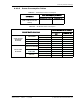
Refer to Table 4-1 for the relationship between antenna numbers and Remote RF
modules.
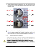
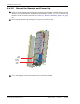
Use the following procedure to install the antenna cable(s):
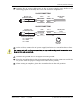
288 Remove the dust cap from the N-type female connector located on the underside
of the unit as shown below.
Table 4-1. Antenna Connectors
Antenna
Connector Label
RF Module Function of Connection Point
Mod A TX0/RX0
2
RF Module A Transmit RF power and primary receive to/from the
antenna
Mod A RX1 RF Module A Diversity receive for RF power from the antenna
Mod B TX0/RX0 RF Module B Transmit RF power and primary receive to/from the
antenna
Mod B RX1 RF Module B Diversity receive for RF power from the antenna
Mod C TX0/RX0 RF Module C Transmit RF power and primary receive to/from the
antenna
Mod C RX1 RF Module C Diversity receive for RF power from the antenna
Mod D TX0/RX0 RF Module D Transmit RF power and primary receive to/from the
antenna
Mod D RX1 RF Module D Diversity receive for RF power from the antenna
2
Mod A/RF Module A is the bottommost Module in a Remote and Mod D/RF Module D is the
topmost module in a Quad-Band Remote.
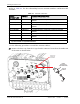
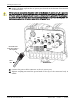
NETWORK
AUX.
MOD A
RX1
MOD A
TX0/RX0
FIBER 1
FIBER 2
MOD B
TX0/RX0
MOD B
RX1
MOD C
TX0/RX0
MOD D
TX0/RX0
MOD C
RX1
MOD D
RX1
POWER
100-240 VAC
50-60 Hz
16 AMPS
Bottom View
Antenna
cable
Lightning
Surge Suppressor
(ships with RF Module)
Surge port
connector
N-type female
Antenna port
for Module A
77073-013