
User Manual Part 2
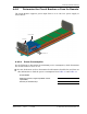

Install any 40W RF Module(s)
FlexWave Prism Host, Remote and EMS 5.1 System Reference Page 123
ADCP-77-073 • Issue 2 • 11/2009 © 2009 ADC Telecommunications, Inc.
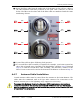
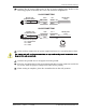
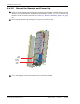
255 Route the fiber cable from the underside of the Remote to the OSP box. Observe
the fiber numbers and their positions in the quad cable connector as shown
below. The fibers at the other end of the fiber cable are numbered with the same
numbering scheme.
266 Secure fiber cable in place following local practices.
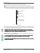
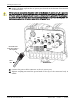
277 If a second fiber cable assembly is required (for example, your Prism system has
three SFPs to handle up to 280 MHz of RF bandwidth), complete Step 22 through
Step 26 to add the second fiber cable assembly, only this time, connect to the
Fiber 2 ProAx connector located at the bottom of the Remote as shown in Step 22.
4.4.7 Antenna Cable Installation
Coaxial antenna cables must be routed from the antenna to the Prism Remote. The
cables must be terminated with an N-Type male connector for connection to the
Remote antenna port or the lightning surge suppressor (accessory).
To comply with Maximum Permissible Exposure (MPE) requirements, the maximum
composite output from the
antenna cannot exceed 1640 Watts EIRP and the antenna
must be permanently installed in a fixed locat
ion that provides at least 6 meters (20 feet)
of separation from all persons.
REV
Fiber 4
SFP2SFP2
77073=047
SFP3SFP3
FWD
Fiber 1
SFP1SFP1
FWD
Fiber 1
SFP1SFP1
REV
Fiber 2
SFP3SFP3
REV
Fiber 2
SFP2SFP2
FWD
Fiber 3
SFP4SFP4
FWD
Fiber 3
SFP4SFP4
REV
Fiber 4