
User Manual Part 2
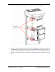

Install any 40W RF Module(s)
FlexWave Prism Host, Remote and EMS 5.1 System Reference Page 115
ADCP-77-073 • Issue 2 • 11/2009 © 2009 ADC Telecommunications, Inc.
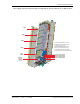
9 Working from the bottom connector up, connect the RF Module cables.
a Connect the RF cable labeled MOD N TX0/RX0 to the TX0/RX0 connector and turn
the thumbscrew to secure the cable to the chassis.
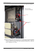
b Connect the MOD N PRIM high-speed cable to the PRIM connector. This
connects the RSI to the Primary DART.
c Connect the Power cable to the PWR connector. This connects the RF Module
to the DC power connection.
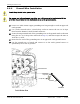
d The Power (PWR) cable and two high-speed-data cables of the upper RF
Module shelf are not be used in a dual-slot installation. Connect the RF cable
labeled MOD N RX1 of the upper RF Module shelf to the connector labeled N/C
on the upper half of the dual-slot module. Use one of the provided cable
ties to secure the MOD N TX0/RX0 RF cable, both high-speed data cables and
the Power (PWR) cable to the RF cable labeled MOD N RX1, ensuring that the
cable bundle will not be pinched or prevent the Remote door from closing.
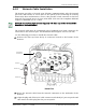
Always connect the Diversity high-speed-data cable, even for non-diversity modules. This prevents the cable
from getting caught between the chassis door and the RF Module.