
User Manual Part 2
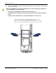

Installing the Remote Unit
Page 104 FlexWave Prism Host, Remote and EMS 5.1 System Reference
© 2009 ADC Telecommunications, Inc ADCP-77-073 • Issue 2 • 11/2009
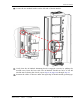
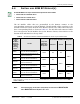
155 Follow these rules when connecting the RF Module cables:
•• At each RF Module shelf, the Power (PWR) cable and two high-speed-data
cables will always be provided.
•• If you are installing a Non-Diversity Chassis, only one RF cable labeled
MOD
N
TX0/RX0
will be populated.
•• Always connect the high-speed-data cable labeled
DIV
. This protects against
the cable getting caught in the chassis door.
•• If you are installing a Diversity Chassis, both RF cables labeled
MOD
N
TX0/RX0
and
MOD
N
RX1
will be populated.
•• For Diversity modules, all cables are to be connected.
•• If you order a Non-Diversity RF Module and are installing it in a Diversity
chassis, connect it as if it was being installed into a Non-Diversity chassis.
•• When you order a Dual SuperDART module, connect both high-speed data
cables (
PRIM
and
DIV
) and the
RF TX0/RX0
cable.
•• Adhere to a minimum bend radius of 1" for all RF cables from the integrated
cable guide to the module.
•• Maintain adequate strain relief distances from connection points to the
module.
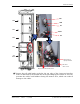
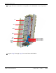
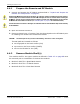
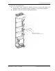
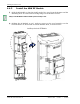
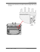
166 Working from the bottom connector up, connect the RF Module cables.
aa If this is a Diversity chassis, connect the RF Diversity cable labeled
MOD
N
RX1
to the
RX1
connector and turn the thumbscrew to secure the cable to the
chassis.
bb Connect the RF cable labeled
MOD
N
TX0/RX0
to the
TX0/RX0
connector and
turn the thumbscrew to secure the cable to the chassis.
cc Connect the
MOD N DIV
high-speed-data cable to the
DIV
connector. This
connects the Remote SeRF interface board (RSI) to the Diversity DART.
dd Connect the
MOD N PRIM
high-speed cable to the
PRIM
connector. This connects
the RSI to the Primary DART.
ee Connect the Power cable to the
PWR
connector. This connects the RF Module to
the DC power connection.
Always connect the Diversity high- speed- data cable, even for non- diversity modules.
This prevents the
cable from getting caught between the chassis door and the RF
Module.