
User Manual Part 1

Installing the Host Unit
Page 84 FlexWave Prism Host, Remote and EMS 5.1 System Reference
© 2009 ADC Telecommunications, Inc ADCP-77-073 • Issue 2 • 11/2009
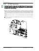
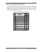
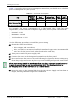
Table 3-2 provides a Host power consumption matrix that you should use to calculate
power consumption for your system.
* Add 1W for each SFP added
For example, the power consumption of a fully-loaded Host, with four Dual
SuperDARTs, a SeRF card (that comprises eight SFPs), and a System card would be:
•• Nominal—131W
•• Maximum—148.4W
•• 15% Headroom—171W
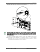
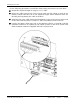
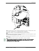
Use the following procedure to install the power wiring:
600 Obtain the items listed below:
•• Wire stripper and screwdriver
•• Wire, #18 AWG (1.00 mm) red and black insulated copper wire. Recommended
wire size for the power leads, when fused in the same bay.
611 Turn power switch on power supply OFF.
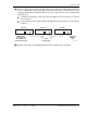
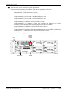
622 Connect the wires to the designated terminals on the fuse panel.
633 Dress and secure the wires to the rack following local practice. Route wiring away
from sharp edges and secure in place to prevent chaffing and provide strain relief.
644 Route the wires to the terminal block on the Host Power Supply and cut them to
length, allowing sufficient length for termination.
Table 3-2. Host Power Consumption
PCB
Classic or
Single
SuperDART
Dual
SuperDART
System Card
(including Fans)
SeRF
(1 SFP)
SeRF
(8 SFPs)*
Power Consumption
Nominal 18.7W 23W 12W 23W 30W
Maximu
m
20W 26W 12.4W 25W 32W
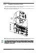
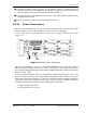
All DC input wiring should be routed away from any sharp edges and properly secured
in place to preve
nt chafing and to provide strain relief. This may be achieved by
tie- wrapping wires to the rack frame
or by a similar means.