
User Manual Part 1

Install the Host
FlexWave Prism Host, Remote and EMS 5.1 System Reference Page 83
ADCP-77-073 • Issue 2 • 11/2009 © 2009 ADC Telecommunications, Inc.
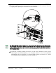
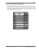
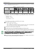
577 Connect the Minor alarm wire pair to the MINOR COM/NC or MINOR COM/NO
terminals (whichever is required by the alarm system) on the Host System card
alarm terminal connector (as shown above and in Table 3-1).
588 Connect the Major and Minor alarm wire pairs to the appropriate terminals on the
external alarm system.
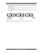
599 Dress and secure cable per standard industry practice.
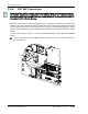
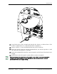
3.3.11 Power Connections
The Host has a modular DC to DC power supply located on the lower left side of the
chassis, which is secured by turning its screws clock-wise until tight.
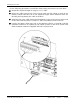
An On/Off switch is provided on the Host power supply module front panel
(Figure 3-3).
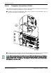
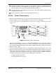
Figure 3-3. Host Power Connector
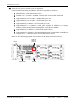
The Host is powered by ± 20 to ± 60 Vdc power (nominal ± 24 or ± 48 Vdc), which is
fed to the Host through a connector located on the front of the module. Power to the
Host must be supplied through a fuse panel (available separately). Each Host must be
protected with a fuse.
A three position terminal block is provided for connecting the power wires. The
power is fed to the Host Power Supply module through the Power Connector located
on the Host front panel (Figure 3-3). Power to the Host must be supplied through a
fuse panel such as the 20 position PowerWorx GMT Fuse Panel (available separately)
and the power must be protected with an appropriate GMT fuse:
•• 5 Amp GMT fuse for 48Vdc
•• 10 Amp GMT fuse for 24 Vdc
Power
Connector
DC Power
Switch
77073-069