
User Manual Part 1

Install the Host
FlexWave Prism Host, Remote and EMS 5.1 System Reference Page 79
ADCP-77-073 • Issue 2 • 11/2009 © 2009 ADC Telecommunications, Inc.
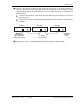
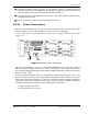
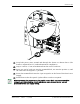
499 Connect the interface cables to the other Hosts that are to be daisy-chained to
Host 1. A diagram of typical EXT REF interface connections is shown below. At the
stopping point where no further Hosts are to be connected, the OUT would be left
unconnected:
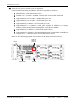
aa Connect the interface cable from the EXT REF OUT port on Host 1 to the IN
port on Host 2.
bb Connect the interface cable from the EXT REF OUT port on Host 2 to the IN port
on Host 3.
500 Repeat Step 49 for each additional Host that is added to the network.
Host Unit 3 Host Unit 2 Host Unit 1
OUT EXT IN
NET IN NET OUT NET IN NET OUT
77073-034
Coaxial
Interface Cables
To Next Host Unit
(Note: No EXT OUT
connection at last Host)
OUT EXT IN OUT EXT IN
REF Clock
Input