
User Manual Part 1
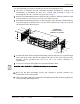
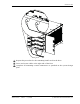
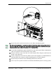

Installing the Host Unit
Page 76 FlexWave Prism Host, Remote and EMS 5.1 System Reference
© 2009 ADC Telecommunications, Inc ADCP-77-073 • Issue 2 • 11/2009
3.3.7.2 Optical Connections For Systems With a WDM
Use the following procedure to connect the optical fibers when a WDM module is
installed with the Host.
377 Obtain a patch cord that is of sufficient length to reach from the WDM module to
the fiber distribution panel.
388 Remove the dust cap from the WDM port on the WDM module and from the patch
cord connector that will be connected to the WDM module.
399 Clean the patch cord connector (follow patch cord supplier’s recommendations).
400 Insert the connector into the WDM port on the WDM module.
411 Obtain two patch cords that are of sufficient length to reach from the WDM
module to the Host.
422 Designate one of the patch cords as the forward path link and the other as the
reverse path link and attach an identification label or tag next to the connector.
433 Remove the dust caps from the Host SeRF SFP optical ports and from the patch
cord connectors that will be connected to the SeRF SFP optical ports.
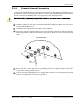
444 Connect the LC attenuator (see Figure 3-2 on Page 73) to the patch cord.
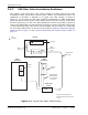
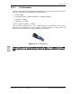
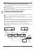
455 Refer to the following diagram to understand the fiber optic connections to the
WDM module.
WDM module ports are labeled FWD, REV, TEST, and WDM.
Fiber Distribution
Panel (FDP)
X
X
Host Unit 1
PORT 8
FWD
PORT 8
REV
REV
path
FWD
path
Wavelength
Division
Multiplexers
1234
PORT 1
FWD
PORT 1
REV
Host Unit 2
REV
path
FWD
path
77073-065
To/From
Remote Unit 1
To/From
Remote Unit 1
Host Unit 1
(Bi-Directional Fiber
Link With Remote Unit)
Host Unit 1
(Bi-Directional Fiber
Link With Remote Unit)
PORT 1
FWD
PORT 1
REV
REV
path
FWD
path
1234
TestTest
1234
Test
Fiber Distribution
Panel (FDP)
X
To/From
Remote Unit 2
Host Unit 2
(Bi-Directional Fiber
Link With Remote Unit)