
User Manual Part 1
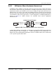

Prism System Components
Page 48 FlexWave Prism Host, Remote and EMS 5.1 System Reference
© 2009 ADC Telecommunications, Inc ADCP-77-073 • Issue 2 • 11/2009
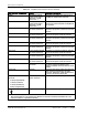
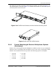
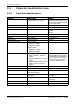
Table 2-3. FlexWave Prism Remote Unit User Interface
User Interface Designation Device Functional Description
FIBER 1 BX5 Duplex Female
single-mode angled
UPC fiber (>50 dB
return loss
1
)
Two fiber pairs which can support up to
140 MHz of duplexed RF spectrum.
FIBER 2 BX5 Duplex Female
single-mode angled
UPC fiber (>50 dB
return loss
1
)
Two additional fiber pairs which can be
used to get to the maximum of 280 MHz of
RF spectrum.
Mod A TX0/RX0
2
N-Type 50-Ohm female
RF coaxial connector
RF Module A connection point for transmit
RF power and primary receive to/from the
antenna.
Mod A RX1 N-Type 50-Ohm female
RF coaxial connector
RF Module A connection point for diversity
receive for RF power from the antenna.
Mod B TX0/RX0 N-Type 50-Ohm female
RF coaxial connector
RF Module B connection point for transmit
RF power and primary receive to/from the
antenna.
Mod B RX1 N-Type 50-Ohm female
RF coaxial connector
RF Module B connection point for diversity
receive for RF power from the antenna.
Mod C TX0/RX0 N-Type 50-Ohm female
RF coaxial connector
RF Module C connection point for transmit
RF power and primary receive to/from the
antenna.
Mod C RX1 N-Type 50-Ohm female
RF coaxial connector
RF Module C connection point for diversity
receive for RF power from the antenna.
Mod D TX0/RX0 N-Type 50-Ohm female
RF coaxial connector
RF Module D connection point for transmit
RF power and primary receive to/from the
antenna.
Mod D RX1 N-Type 50-Ohm female
RF coaxial connector
RF Module D connection point for diversity
receive for RF power from the antenna.
Network Sealed RJ-45 female
connector
Connection point for communication with
the entire connected network: Host,
Remote, and ENET connected devices at the
Remote.
Status LED Red LED At startup, the Status LED is ON (solid red)
prior to being controlled by the SeRF
processor. Otherwise, when the Remote is
in service, the Status LED is OFF.
100/240 VAC
50–60 HZ
16 Amps (Quad-Band)
13 Amps (Tri-Band)
10 Amps (Dual-Band)
6 Amps (Single-Band)
Sealed 3-wire AC
power connector
Connection point for the AC power cord.
Supplied ground lug Connection point for grounding unit.
1
ADC connector specification
2
Mod A/RF Module A is the bottommost Module in a Remote and Mod D/RF Module D is the
topmost module in a Quad-Band Remote.