
User Manual Part 1


FlexWave Prism Host Units
FlexWave Prism Host, Remote and EMS 5.1 System Reference Page 33
ADCP-77-073 • Issue 2 • 11/2009 © 2009 ADC Telecommunications, Inc.
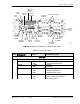
2.2.2 Host Network Connection
The SeRF front panel has a Network port that creates a network connection between
the Host and the network to monitor and configure the FlexWave Prism system
through the FlexWave EMS.
The network interface connection between the Host and the network is supported by
a Gigabit Ethernet (10/100/1000) RJ-45 jack with integrated green ACTIVITY and
LINK LEDs. The Network port supports a maximum cable length of 100 meters (328
feet) to a switch or back-to-back nodes. CAT5 or better cable should be used when
making this connection. The Ethernet connection should not be connected to an
Ethernet circuit used outside the building.
For further information on using the Network port and the FlexWave EMS, see
“System Setup and Management.”
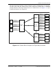
2.2.3 Host RF Signal Connections
The RF signal connections between the Host DART cards and the BTS are supported
through two (FWD RF IN and REV RF OUT) QMA-Type female connectors. One
connector is used for the forward path RF signal. The other connector is used for the
reverse path RF signal. In some installations, it may be necessary to install a
Conditioning Panel and/or Duplexing Panel (accessory items) to support the interface
between the Host and the BTS. The Host should be as close as possible to the BTS to
minimize cable losses.
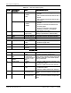
DART CARD
15 PWR (LED) • GREEN
•OFF
• Card is powered.
• No power present at card.
16 STATUS (LED) • GREEN
•RED
• YELLOW
•OK
• Major Alarm
• ALC activated
17 REV RF OUT QMA-Type female RF
coaxial connector
Output connection point for the primary
reverse path RF coaxial cable
18 FWD RF IN QMA-Type female RF
coaxial connector
Input connection point for the forward path
RF coaxial cable
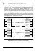
19 & 20 Slots 1 - 8 • Classic DARTs
•Single
SuperDARTs
• Dual SuperDARTs
• Classic DARTS and Single SuperDARTs can
occupy Slots 1 - 8 (usually a 6-Timeslot
DART)
• Dual SuperDARTs can occupy Slots 1/3,
5/7, 2/4 or 6/8 (12-Timeslot DARTs)
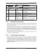
Table 2-1. Host User Interface (Cont.)
Ref No User Interface
Designation
Device Functional Description