
User Manual Part 1

FlexWave Prism Host Units
FlexWave Prism Host, Remote and EMS 5.1 System Reference Page 31
ADCP-77-073 • Issue 2 • 11/2009 © 2009 ADC Telecommunications, Inc.
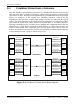
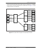
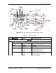
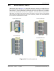
Figure 2-3. User Interface on Host Front Panel
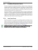
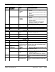
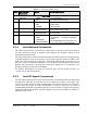
Table 2-1. Host User Interface
Ref No User Interface
Designation
Device Functional Description
SeRF Card
1 SeRF Card LEDs
ALARM • ON
•OFF
• Initial bootup sequence
• System operation normal
SYNTH • GREEN
•RED
•Locked
•Unlocked
SW FLT • ON
•OFF
•RED
• Initial bootup sequence
• Software operating OK
• Software failed to start
PWR • GREEN
•RED
•OFF
• Power OK and operating properly
• Power supply out of tolerance
• No power present
(3) Optical Port
FWD & REV
Connectors 1 -8
(5) Craft
Interface
(4) Network
Interface
(12) REF LED
Indicators
(1) SeRF CARD
ALARM LEDS
(9) System Card
Power LED
Indicator
(7) DC Power
ON/OFF Switch
(8) Power
Connector
(13 & 14)
REF OUT
& IN Jacks
(10) Host
Alarm
Outputs
(11) Remote
Alarm Outputs
(6) Power
LED Indicator
(18) FWD RF
IN Jack
(16) DART Status
LED Indicator
(15) DART Power
LED Indicator
(17) REV RF
OUT Jack
(19) Two 12-Timeslot DARTs
(2) SFP RX
and TX LEDs
77073-032
(20) Four
6-Timeslot
DARTs