
User's Manual


DART Card Replacement/Installation Procedure
FlexWave Prism Host, Remote and EMS 5.1 System Reference Page 327
ADCP-77-073 • Issue 2 • 11/2009 © 2009 ADC Telecommunications, Inc.
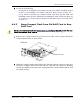
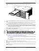
55 Slide the DART card into the Host chassis until it is firmly seated.
66 Secure the DART card to the front of the enclosure using the two thumb screws.
77 Obtain the required lengths of high performance, flexible, low loss 50-ohm coaxial
communications cable (RG-400 or equivalent) for all coaxial connections.
88 Route the forward and reverse path coaxial cables between the Host and the BTS
interface (per system design plan) and cut to the required length. Allow sufficient
slack for dressing and organizing cables at the Host and for installing an external
attenuator in the forward path link.
99 Terminate each cable with an QMA-type male connector following the connector
supplier’s recommendations.
100 If required, install an external attenuator in the forward path.
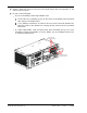
111 Connect the forward and reverse path cables as shown as shown in Step 21 in
Section 3.3.5, Coaxial Cable Connections, on page 70:
aa Connect the forward path cable to the FWD RF IN connector on the Host DART
front panel.
bb Connect the reverse path cable to the REV RF OUT connector on the Host DART
front panel.
122 Dress and secure cables at the right side of the Host.
133 Complete all remaining coaxial connections as specified in the system design
plan.
144 Notify the NOC or alarm monitoring system operator that the DART card is ready
for operation.
The composite forward path RF signal level at the Host must be between –25 and + 5
dBm. Do not c
onnect the forward path cable until the composite forward path RF signal
level is measured and the am
ount of external attenuation required is determined.
22401-A