
User's Manual
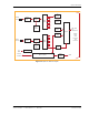


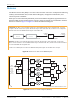
Table Of Contents
- Table of Contents
- Preface
- InterReach Fusion Wideband System Description
- System Overview
- System Hardware
- System OA&M Capabilities
- System Connectivity
- System Operation
- System Specifications
- RF End-to-End Performance
- 2100/1800 RAU (FSN-W1-2118-1)
- 2100 HP/1800 HP (FSN-W1-2118-1-HP)
- 2100 HP/2600 HP (FSN-W1-2126-1-HP)
- 2100 High Power RAU (FSN-W1-21HP-1)
- 1900/AWS RAU (FSN-W1-1921-1)
- 800/850/1900 RAU (FSN-W2-808519-1)
- 700/AWS RAU (FSN-W2-7021-1)
- 700/700 (Upper C) MIMO RAU (FSN-W2-7575-1)
- 700/700 (Lower ABC) MIMO RAU (FSN-W2-7070-1)
- 700 ABC/AWS HP/AWS HP RAU (FSN-W4-702121-1-HP)
- 700 UC/AWS HP/AWS HP RAU (FSN-W4-752121-1-HP)
- 850/1900 HP/AWS HP RAU (FSN-W5-851921-1-HP)
- 2500/2500 RAU (FSN-2525-1-TDD)
- 2600/2600 RAU (FSN-W3-2626-1)
- Fusion Wideband Main Hub
- Fusion Wideband Expansion Hub
- Remote Access Unit
- Designing a Fusion Wideband Solution
- Design Overview
- Downlink RSSI Design Goal
- Maximum Output Power Per Carrier
- 700/AWS RAU (FSN-W2-7021-1)
- 700 MHz (Upper C) MIMO RAU (FSN-W2-7575-1)
- 700 MHz (Lower ABC) MIMO RAU (FSN-W2-7070-1)
- 700 ABC/AWS HP/AWS HP RAU (FSN-W4-702121-1-HP)
- 700 UC/AWS HP/AWS HP RAU (FSN-W4-752121-1-HP)
- 800/850/1900 RAU (FSN-W2-808519-1)
- 850/1900 HP/AWS HP RAU (FSN-W5-851921-1-HP)
- 1900/AWS RAU (FSN-W1-1921-1)
- 2100/1800 RAU (FSN-W1-2118-1)
- 2100 HP/1800 HP RAU (FSN-W1-2118-1-HP)
- 2100 HP/2600 HP RAU (FSN-W1-2126-1-HP)
- 2100 High Power RAU (FSN-W1-21HP-1)
- 2500/2500 TDD RAU (FSN-2525-1-TDD)
- 2600 MHz MIMO RAU (FSN-W3-2626-1)
- Designing for Capacity Growth
- System Gain
- Estimating RF Coverage
- Link Budget Analysis
- Optical Power Budget
- Connecting a Main Hub to a Base Station
- Installing Fusion Wideband
- Installation Requirements
- Safety Precautions
- Preparing for System Installation
- Installing a Fusion Wideband Main Hub
- Installing a Fusion Wideband Main Hub in a Rack
- Installing an Optional Cable Manager in the Rack
- Installing a Main Hub Using the 12” Wall-Mounted Rack (PN 4712)
- Installing a Fusion Wideband Main Hub Directly to the Wall
- Connecting the Fiber Cables to the Main Hub
- Making Power Connections
- Optional Connection to DC Power Source
- Power on the Main Hub
- Installing Expansion Hubs
- Installing the Expansion Hub in a Rack
- Installing an Expansion Hub Using the 12” Wall-Mounted Rack
- Installing an Expansion Hub Directly to the Wall
- Installing an Optional Cable Manager in the Rack
- Powering on the Expansion Hub
- Connecting the Fiber Cables to the Expansion Hub
- Connecting the 75 Ohm CATV Cables
- Troubleshooting Expansion Hub LEDs During Installation
- Installing RAUs
- Configuring the Fusion Wideband System
- Splicing Fiber Optic Cable
- Interfacing the Fusion Wideband Main Hub to an RF Source
- Connecting a Fusion Wideband Main Hub to an In-Building BTS
- Connecting a Duplex Base Station to a Fusion Wideband Main Hub
- Connecting a Fusion Wideband Main Hub RF Band to Multiple BTSs
- Connecting a Fusion Wideband Main Hub to a Roof-Top Antenna
- Connecting a Fusion Wideband Main Hub to Flexwave Focus
- Connecting Multiple Fusion Wideband Main Hubs to an RF Source
- Connecting Contact Alarms to a Fusion Wideband System
- Alarm Monitoring Connectivity Options
- Replacing Fusion Wideband Components
- Maintenance and Troubleshooting
- Appendix A: Cables and Connectors
- Appendix B: Compliance
- Appendix C: Faults, Warnings, Status Tables for Fusion, Fusion Wideband, Fusion SingleStar
- Appendix D: Contacting TE Connectivity

Expansion Hub Overview
InterReach Fusion Wideband Installation, Operation, and Reference Manual Page 45
D-620616-0-20 Rev K • TECP-77-044 Issue 9 • March 2015 © 2015 TE Connectivity
Optical Fiber Uplink/Downlink Connectors
The optical fiber uplink/downlink port transmits and receives optical signals between the
Expansion Hub and the Main Hub using industry-standard SMF or MMF cable. The fiber port has
two female SC/APC connectors:
• Optical Fiber
Up
link Connector—The UPLINK connector transmits (output) uplink optical
signals to the Main Hub.
• Optical Fiber Down
link Connector—The DOWNLINK connector receives (input) downlink
optical signals from the Main Hub.
CAUTION! To avoid damaging the Expansion Hub’s fiber connector ports, use only SC/APC fiber cable
connectors. Additionally, use only SC/APC fiber connectors throughout the fiber network,
including fiber distribution panels. This is critical for ensuring system performance.
LED Indicators
The unit’s front panel LEDs indicate fault conditions and commanded or fault lockouts. The LEDs
do not indicate warnings or whether the system test has been performed. Only use the LEDs to
provide basic information or as a backup when you are not using AdminBrowser.
Upon power up, the Expansion Hub goes through a five-second test to check
the LED lamps.
During this time, the LEDs blink through the states shown in Table 35, letting you visually verify
that the LED lamps and the firmware are functioning properly.
NOTE: Refer to “Maintenance and Troubleshooting” on page 181 for troubleshooting using the LEDs.
Unit Status and DL/UL STATUS LEDs
The Expansion Hub unit status and DL/UL STATUS LEDs can be in one of the states shown in
Table 35. These LEDs can be:
Steady green
Steady red
Off
Table 35. Expansion Hub Unit Status and DL/UL STATUS LED States
LED State Indicates
Green/Green
Green/Green
• The Expansion Hub is connected to
power and all power
supplies are operating.
• The Expansion Hub is not reporting a fault or lockout
condition; but the system test may need to be performed or
a warning condition could exist (use AdminManager to
determine this).
• Optical power received is above minimum (the Main Hub is
connected) although the cable optical loss may be greater
than recommended maximum.
• Optical power transmitted (uplink laser) is normal and
communications with the Main Hub are normal.
POWER
EH STATUS
DL STATUS
UL STATUS