
User's Manual

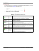

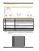


Table Of Contents
- Table of Contents
- Preface
- InterReach Fusion Wideband System Description
- System Overview
- System Hardware
- System OA&M Capabilities
- System Connectivity
- System Operation
- System Specifications
- RF End-to-End Performance
- 2100/1800 RAU (FSN-W1-2118-1)
- 2100 HP/1800 HP (FSN-W1-2118-1-HP)
- 2100 HP/2600 HP (FSN-W1-2126-1-HP)
- 2100 High Power RAU (FSN-W1-21HP-1)
- 1900/AWS RAU (FSN-W1-1921-1)
- 800/850/1900 RAU (FSN-W2-808519-1)
- 700/AWS RAU (FSN-W2-7021-1)
- 700/700 (Upper C) MIMO RAU (FSN-W2-7575-1)
- 700/700 (Lower ABC) MIMO RAU (FSN-W2-7070-1)
- 700 ABC/AWS HP/AWS HP RAU (FSN-W4-702121-1-HP)
- 700 UC/AWS HP/AWS HP RAU (FSN-W4-752121-1-HP)
- 850/1900 HP/AWS HP RAU (FSN-W5-851921-1-HP)
- 2500/2500 RAU (FSN-2525-1-TDD)
- 2600/2600 RAU (FSN-W3-2626-1)
- Fusion Wideband Main Hub
- Fusion Wideband Expansion Hub
- Remote Access Unit
- Designing a Fusion Wideband Solution
- Design Overview
- Downlink RSSI Design Goal
- Maximum Output Power Per Carrier
- 700/AWS RAU (FSN-W2-7021-1)
- 700 MHz (Upper C) MIMO RAU (FSN-W2-7575-1)
- 700 MHz (Lower ABC) MIMO RAU (FSN-W2-7070-1)
- 700 ABC/AWS HP/AWS HP RAU (FSN-W4-702121-1-HP)
- 700 UC/AWS HP/AWS HP RAU (FSN-W4-752121-1-HP)
- 800/850/1900 RAU (FSN-W2-808519-1)
- 850/1900 HP/AWS HP RAU (FSN-W5-851921-1-HP)
- 1900/AWS RAU (FSN-W1-1921-1)
- 2100/1800 RAU (FSN-W1-2118-1)
- 2100 HP/1800 HP RAU (FSN-W1-2118-1-HP)
- 2100 HP/2600 HP RAU (FSN-W1-2126-1-HP)
- 2100 High Power RAU (FSN-W1-21HP-1)
- 2500/2500 TDD RAU (FSN-2525-1-TDD)
- 2600 MHz MIMO RAU (FSN-W3-2626-1)
- Designing for Capacity Growth
- System Gain
- Estimating RF Coverage
- Link Budget Analysis
- Optical Power Budget
- Connecting a Main Hub to a Base Station
- Installing Fusion Wideband
- Installation Requirements
- Safety Precautions
- Preparing for System Installation
- Installing a Fusion Wideband Main Hub
- Installing a Fusion Wideband Main Hub in a Rack
- Installing an Optional Cable Manager in the Rack
- Installing a Main Hub Using the 12” Wall-Mounted Rack (PN 4712)
- Installing a Fusion Wideband Main Hub Directly to the Wall
- Connecting the Fiber Cables to the Main Hub
- Making Power Connections
- Optional Connection to DC Power Source
- Power on the Main Hub
- Installing Expansion Hubs
- Installing the Expansion Hub in a Rack
- Installing an Expansion Hub Using the 12” Wall-Mounted Rack
- Installing an Expansion Hub Directly to the Wall
- Installing an Optional Cable Manager in the Rack
- Powering on the Expansion Hub
- Connecting the Fiber Cables to the Expansion Hub
- Connecting the 75 Ohm CATV Cables
- Troubleshooting Expansion Hub LEDs During Installation
- Installing RAUs
- Configuring the Fusion Wideband System
- Splicing Fiber Optic Cable
- Interfacing the Fusion Wideband Main Hub to an RF Source
- Connecting a Fusion Wideband Main Hub to an In-Building BTS
- Connecting a Duplex Base Station to a Fusion Wideband Main Hub
- Connecting a Fusion Wideband Main Hub RF Band to Multiple BTSs
- Connecting a Fusion Wideband Main Hub to a Roof-Top Antenna
- Connecting a Fusion Wideband Main Hub to Flexwave Focus
- Connecting Multiple Fusion Wideband Main Hubs to an RF Source
- Connecting Contact Alarms to a Fusion Wideband System
- Alarm Monitoring Connectivity Options
- Replacing Fusion Wideband Components
- Maintenance and Troubleshooting
- Appendix A: Cables and Connectors
- Appendix B: Compliance
- Appendix C: Faults, Warnings, Status Tables for Fusion, Fusion Wideband, Fusion SingleStar
- Appendix D: Contacting TE Connectivity

Fusion Wideband Main Hub Front Panel
InterReach Fusion Wideband Installation, Operation, and Reference Manual Page 33
D-620616-0-20 Rev K • TECP-77-044 Issue 9 • March 2015 © 2015 TE Connectivity
Uplink/Downlink Optical-Fiber Ports
The uplink/downlink optical-fiber ports transmit and receive optical signals between the Main
Hub and up to four Expansion Hubs using industry-standard SMF or MMF cable. There are four
fiber ports on the front panel of the Main Hub—one port per Expansion Hub. Each optical-fiber
port has two female SC/APC connectors:
• UPLINK Co
nnector—receives the uplink optical signals from an Expansion Hub.
• DOWNLINK Connector—transmits the dow
nlink optical signals to an Expansion Hub.
CAUTION! To avoid damaging the Main Hub’s fiber connector ports, use only SC/APC fiber cable connectors
when using either single-mode or multi-mode fiber. Additionally, it is critical to system
performance that only SC/APC fiber connectors are used throughout the fiber network, including
fiber distribution panels.
Main Hub LED Indicators
The unit’s front panel LEDs indicate faults and commanded or fault lockouts. The LEDs do not
indicate warnings or whether the system test has been performed. Use the LEDs to provide basic
information only, or as a backup when you are not using AdminBrowser.
Upon power up, the Main Hub goes through a 20-second test to check the
LED lamps. During this
time, the LEDs blink through the states shown in Table 31 on page 34, letting you visually verify
t
hat the LED lamps and the firmware are functioning properly. Upon
completion of initialization,
the LEDs stay in one of the first two states shown in Table 31 on page 34.
The Main Hub automatically sends the
program
bands command to all connected RAUs. A
mismatched band causes a fault message to be displayed in AdminBrowser and places the RAU in
a disabled condition.
NOTE: Refer to “Troubleshooting Using LEDs” on page 185 for troubleshooting using the LEDs.
NOTE: AdminBrowser should be used for troubleshooting the system. Only use LEDs for backup or
confirmation. However, if there are communication problems within the system, the LEDs may
provide additional information that is not available using AdminBrowser.