
User's Manual
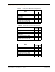
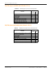

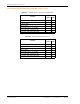


Table Of Contents
- Table of Contents
- Preface
- InterReach Fusion Wideband System Description
- System Overview
- System Hardware
- System OA&M Capabilities
- System Connectivity
- System Operation
- System Specifications
- RF End-to-End Performance
- 2100/1800 RAU (FSN-W1-2118-1)
- 2100 HP/1800 HP (FSN-W1-2118-1-HP)
- 2100 HP/2600 HP (FSN-W1-2126-1-HP)
- 2100 High Power RAU (FSN-W1-21HP-1)
- 1900/AWS RAU (FSN-W1-1921-1)
- 800/850/1900 RAU (FSN-W2-808519-1)
- 700/AWS RAU (FSN-W2-7021-1)
- 700/700 (Upper C) MIMO RAU (FSN-W2-7575-1)
- 700/700 (Lower ABC) MIMO RAU (FSN-W2-7070-1)
- 700 ABC/AWS HP/AWS HP RAU (FSN-W4-702121-1-HP)
- 700 UC/AWS HP/AWS HP RAU (FSN-W4-752121-1-HP)
- 850/1900 HP/AWS HP RAU (FSN-W5-851921-1-HP)
- 2500/2500 RAU (FSN-2525-1-TDD)
- 2600/2600 RAU (FSN-W3-2626-1)
- Fusion Wideband Main Hub
- Fusion Wideband Expansion Hub
- Remote Access Unit
- Designing a Fusion Wideband Solution
- Design Overview
- Downlink RSSI Design Goal
- Maximum Output Power Per Carrier
- 700/AWS RAU (FSN-W2-7021-1)
- 700 MHz (Upper C) MIMO RAU (FSN-W2-7575-1)
- 700 MHz (Lower ABC) MIMO RAU (FSN-W2-7070-1)
- 700 ABC/AWS HP/AWS HP RAU (FSN-W4-702121-1-HP)
- 700 UC/AWS HP/AWS HP RAU (FSN-W4-752121-1-HP)
- 800/850/1900 RAU (FSN-W2-808519-1)
- 850/1900 HP/AWS HP RAU (FSN-W5-851921-1-HP)
- 1900/AWS RAU (FSN-W1-1921-1)
- 2100/1800 RAU (FSN-W1-2118-1)
- 2100 HP/1800 HP RAU (FSN-W1-2118-1-HP)
- 2100 HP/2600 HP RAU (FSN-W1-2126-1-HP)
- 2100 High Power RAU (FSN-W1-21HP-1)
- 2500/2500 TDD RAU (FSN-2525-1-TDD)
- 2600 MHz MIMO RAU (FSN-W3-2626-1)
- Designing for Capacity Growth
- System Gain
- Estimating RF Coverage
- Link Budget Analysis
- Optical Power Budget
- Connecting a Main Hub to a Base Station
- Installing Fusion Wideband
- Installation Requirements
- Safety Precautions
- Preparing for System Installation
- Installing a Fusion Wideband Main Hub
- Installing a Fusion Wideband Main Hub in a Rack
- Installing an Optional Cable Manager in the Rack
- Installing a Main Hub Using the 12” Wall-Mounted Rack (PN 4712)
- Installing a Fusion Wideband Main Hub Directly to the Wall
- Connecting the Fiber Cables to the Main Hub
- Making Power Connections
- Optional Connection to DC Power Source
- Power on the Main Hub
- Installing Expansion Hubs
- Installing the Expansion Hub in a Rack
- Installing an Expansion Hub Using the 12” Wall-Mounted Rack
- Installing an Expansion Hub Directly to the Wall
- Installing an Optional Cable Manager in the Rack
- Powering on the Expansion Hub
- Connecting the Fiber Cables to the Expansion Hub
- Connecting the 75 Ohm CATV Cables
- Troubleshooting Expansion Hub LEDs During Installation
- Installing RAUs
- Configuring the Fusion Wideband System
- Splicing Fiber Optic Cable
- Interfacing the Fusion Wideband Main Hub to an RF Source
- Connecting a Fusion Wideband Main Hub to an In-Building BTS
- Connecting a Duplex Base Station to a Fusion Wideband Main Hub
- Connecting a Fusion Wideband Main Hub RF Band to Multiple BTSs
- Connecting a Fusion Wideband Main Hub to a Roof-Top Antenna
- Connecting a Fusion Wideband Main Hub to Flexwave Focus
- Connecting Multiple Fusion Wideband Main Hubs to an RF Source
- Connecting Contact Alarms to a Fusion Wideband System
- Alarm Monitoring Connectivity Options
- Replacing Fusion Wideband Components
- Maintenance and Troubleshooting
- Appendix A: Cables and Connectors
- Appendix B: Compliance
- Appendix C: Faults, Warnings, Status Tables for Fusion, Fusion Wideband, Fusion SingleStar
- Appendix D: Contacting TE Connectivity

Fusion Wideband Main Hub
Page 32 InterReach Fusion Wideband Installation, Operation, and Reference Manual
© 2015 TE Connectivity D-620616-0-20 Rev K • TECP-77-044 Issue 9 • March 2015
FUSION WIDEBAND MAIN HUB FRONT PANEL
Ref # Component Function
Port 1 - Port 4 Four fiber optic ports with corresponding
fiber port LEDs (one LED per port)
1, 8 UPLINK and DOWNLINK ports One standard female SC/APC connector per port for MMF/SMF inpu
t (UPLINK)
and one standard female SC/APC connector per port for MMF/SMF output
(DOWNLINK). See “Uplink/Downlink Optical-Fiber Ports” on page 33
.
2 STATUS LED (unlabeled) One LED per port for port link status and downstream unit status
; see “Fiber Port
LEDs” on page 35.
3 POWER LED See “Main Hub LED Indicators” on page 33.
4 MAIN HUB STATUS LED
5 ADMIN/LAN connector One RJ-45 female connector for system communication and diagnostics u
sing a
PC/laptop with direct connect or using a LAN switch; see “Communications
RS-232 Serial Connector” on page 35.
6 Modem connector One 9-pin D-sub male connector for system
remote dial-
up communication and
diagnostics using a modem; see “Communications RS-232 Serial Connector” on
page 35.
7 Power switch Turns the Fusion Wideband Main Hub on or off.
POWER
MAIN HUB
STATUS
UPLINK
DOWNLINK
PORT 1
PORT 2
PORT 3
PORT 4
POWER
InterReach
Wideband Fusion
Main Hub
ADMIN LANMODEM
1
3
567
Unit is not shown to scale.
2
4
8