
User's Manual


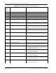


Table Of Contents
- Table of Contents
- Preface
- InterReach Fusion Wideband System Description
- System Overview
- System Hardware
- System OA&M Capabilities
- System Connectivity
- System Operation
- System Specifications
- RF End-to-End Performance
- 2100/1800 RAU (FSN-W1-2118-1)
- 2100 HP/1800 HP (FSN-W1-2118-1-HP)
- 2100 HP/2600 HP (FSN-W1-2126-1-HP)
- 2100 High Power RAU (FSN-W1-21HP-1)
- 1900/AWS RAU (FSN-W1-1921-1)
- 800/850/1900 RAU (FSN-W2-808519-1)
- 700/AWS RAU (FSN-W2-7021-1)
- 700/700 (Upper C) MIMO RAU (FSN-W2-7575-1)
- 700/700 (Lower ABC) MIMO RAU (FSN-W2-7070-1)
- 700 ABC/AWS HP/AWS HP RAU (FSN-W4-702121-1-HP)
- 700 UC/AWS HP/AWS HP RAU (FSN-W4-752121-1-HP)
- 850/1900 HP/AWS HP RAU (FSN-W5-851921-1-HP)
- 2500/2500 RAU (FSN-2525-1-TDD)
- 2600/2600 RAU (FSN-W3-2626-1)
- Fusion Wideband Main Hub
- Fusion Wideband Expansion Hub
- Remote Access Unit
- Designing a Fusion Wideband Solution
- Design Overview
- Downlink RSSI Design Goal
- Maximum Output Power Per Carrier
- 700/AWS RAU (FSN-W2-7021-1)
- 700 MHz (Upper C) MIMO RAU (FSN-W2-7575-1)
- 700 MHz (Lower ABC) MIMO RAU (FSN-W2-7070-1)
- 700 ABC/AWS HP/AWS HP RAU (FSN-W4-702121-1-HP)
- 700 UC/AWS HP/AWS HP RAU (FSN-W4-752121-1-HP)
- 800/850/1900 RAU (FSN-W2-808519-1)
- 850/1900 HP/AWS HP RAU (FSN-W5-851921-1-HP)
- 1900/AWS RAU (FSN-W1-1921-1)
- 2100/1800 RAU (FSN-W1-2118-1)
- 2100 HP/1800 HP RAU (FSN-W1-2118-1-HP)
- 2100 HP/2600 HP RAU (FSN-W1-2126-1-HP)
- 2100 High Power RAU (FSN-W1-21HP-1)
- 2500/2500 TDD RAU (FSN-2525-1-TDD)
- 2600 MHz MIMO RAU (FSN-W3-2626-1)
- Designing for Capacity Growth
- System Gain
- Estimating RF Coverage
- Link Budget Analysis
- Optical Power Budget
- Connecting a Main Hub to a Base Station
- Installing Fusion Wideband
- Installation Requirements
- Safety Precautions
- Preparing for System Installation
- Installing a Fusion Wideband Main Hub
- Installing a Fusion Wideband Main Hub in a Rack
- Installing an Optional Cable Manager in the Rack
- Installing a Main Hub Using the 12” Wall-Mounted Rack (PN 4712)
- Installing a Fusion Wideband Main Hub Directly to the Wall
- Connecting the Fiber Cables to the Main Hub
- Making Power Connections
- Optional Connection to DC Power Source
- Power on the Main Hub
- Installing Expansion Hubs
- Installing the Expansion Hub in a Rack
- Installing an Expansion Hub Using the 12” Wall-Mounted Rack
- Installing an Expansion Hub Directly to the Wall
- Installing an Optional Cable Manager in the Rack
- Powering on the Expansion Hub
- Connecting the Fiber Cables to the Expansion Hub
- Connecting the 75 Ohm CATV Cables
- Troubleshooting Expansion Hub LEDs During Installation
- Installing RAUs
- Configuring the Fusion Wideband System
- Splicing Fiber Optic Cable
- Interfacing the Fusion Wideband Main Hub to an RF Source
- Connecting a Fusion Wideband Main Hub to an In-Building BTS
- Connecting a Duplex Base Station to a Fusion Wideband Main Hub
- Connecting a Fusion Wideband Main Hub RF Band to Multiple BTSs
- Connecting a Fusion Wideband Main Hub to a Roof-Top Antenna
- Connecting a Fusion Wideband Main Hub to Flexwave Focus
- Connecting Multiple Fusion Wideband Main Hubs to an RF Source
- Connecting Contact Alarms to a Fusion Wideband System
- Alarm Monitoring Connectivity Options
- Replacing Fusion Wideband Components
- Maintenance and Troubleshooting
- Appendix A: Cables and Connectors
- Appendix B: Compliance
- Appendix C: Faults, Warnings, Status Tables for Fusion, Fusion Wideband, Fusion SingleStar
- Appendix D: Contacting TE Connectivity

Appendix C: Faults, Warnings, Status Tables for Fusion, Fusion Wideband, Fusion SingleStar
Page 218 InterReach Fusion Wideband Installation, Operation, and Reference Manual
© 2015 TE Connectivity D-620616-0-20 Rev K • TECP-77-044 Issue 9 • March 2015
Table 107. Warnings/Status Messages for Main Hubs
Message
Number/
Default
Description Reason/Action
[M01]/S Fan 1 failure. Check the fan for rotation, air flow blockage, and dust. Re
place the
Hub on high temperature warning.
[M02]/S Fan 2 failure. Check the fan for rotation, air flow blockage, and dust.
Re
place the
Hub on high temperature warning.
[M03]/S 54 VDC Pwr Supply Fan failure. Check the fan for rotation, air flow blockage, and dust. Re
place the
Hub on high temperature warning.
[M04]/W 5 VDC Monitor. DC power out of range, replace the Hub.
[M05]/W 9 VDC
Monitor. DC power out of range, replace the Hub.
[M06]/W 54 VDC
Monitor. DC power out of range, replace the Hub.
[M07]/W 3 VDC
Monitor. DC power out of range, replace the Hub.
[M08]/W 12 VDC
Monitor. DC power out of range, replace the Hub.
[M09]/W Temperature High. Re
duce ambient temperature, check for air flow blockage, fan
rotation.
[M10]/W -5 VDC
Monitor. DC power is out of range, r
e
place the Hub.
[M11]/W High laser current. Output laser failure possible, replace the Hub when possible.
[M12]/W DL path loss is too high Replace the Hub.
[M13]/S Low input optical (Port 1). Check the uplink fiber.
[M14]/S Low input optical (Port 2). Check the uplink fiber.
[M15]/S Low input optical (Port 3). Check the uplink fiber.
[M16]/S Low input optical (Port 4). Check the uplink fiber.
[M17]/S Hardware failure (Test Tone
PLL Band
1). Unable to perform DL system test.
[M18]/S Hardware failure (Test Tone Too High Band 1). Unable to perform DL system test.
[M19]/S Hardware failure (Test Tone Too Low Band 1). Unable to perform DL system test.
[M20]/W Overdrive limiter active (Band 1). Reduce input signal power to avoid potential component damage.
[M21]/W CEMark limiter at maximum (Band 1). Reduce input signal power to avoid drop in
system gain.
[M22]/W No DL test
tone (Band 1). Hub DL gain is low.
[M23]/S No UL test tone (Band 1). Hub UL path gain is low.
[M24]/S Problem detected in the system. Contact TE Support for more information.
[M25]/S Hardware failure (Test Tone
PLL Band
2). Unable to perform DL system test. Replace the hub when possible.
[M26]/S Hardware failure (Test Tone Too High Band 2). Unable to perform DL system test. Replace the hub when possible.
[M27]/S Hardware failure (Test Tone Too Low Band 2). Unable to perform DL system test. Replace the hub when possible.
[M28]/W Overdrive limiter active (Band 2). Reduce input signal power to avoid potential component damage.
[M29]/W CEMark limiter at maximum (Band 2). Reduce input signal power to avoid drop in
system gain.
[M30]/W No DL test
tone (Band 2). Hub DL path gain is low.
[M31]/S No UL test tone (Band 2). Hub UL path gain is low.
[M32]/S Problem detected in the system. Contact TE Support for more information.
[M33]/S Hardware failure (Test Tone
PLL Band
3). Unable to perform DL system test.
[M34]/S Hardware failure (Test Tone Too High Band 3). Unable to perform DL system test.
[M35]/S Hardware failure (Test Tone Too Low Band 3). Unable to perform DL system test.
[M36]/W Overdrive limiter active (Band 3). Reduce input signal power to avoid potential component damage.