
User's Manual
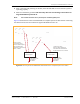

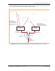
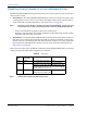
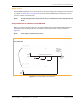
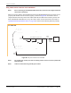


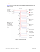

Table Of Contents
- Table of Contents
- Preface
- InterReach Fusion Wideband System Description
- System Overview
- System Hardware
- System OA&M Capabilities
- System Connectivity
- System Operation
- System Specifications
- RF End-to-End Performance
- 2100/1800 RAU (FSN-W1-2118-1)
- 2100 HP/1800 HP (FSN-W1-2118-1-HP)
- 2100 HP/2600 HP (FSN-W1-2126-1-HP)
- 2100 High Power RAU (FSN-W1-21HP-1)
- 1900/AWS RAU (FSN-W1-1921-1)
- 800/850/1900 RAU (FSN-W2-808519-1)
- 700/AWS RAU (FSN-W2-7021-1)
- 700/700 (Upper C) MIMO RAU (FSN-W2-7575-1)
- 700/700 (Lower ABC) MIMO RAU (FSN-W2-7070-1)
- 700 ABC/AWS HP/AWS HP RAU (FSN-W4-702121-1-HP)
- 700 UC/AWS HP/AWS HP RAU (FSN-W4-752121-1-HP)
- 850/1900 HP/AWS HP RAU (FSN-W5-851921-1-HP)
- 2500/2500 RAU (FSN-2525-1-TDD)
- 2600/2600 RAU (FSN-W3-2626-1)
- Fusion Wideband Main Hub
- Fusion Wideband Expansion Hub
- Remote Access Unit
- Designing a Fusion Wideband Solution
- Design Overview
- Downlink RSSI Design Goal
- Maximum Output Power Per Carrier
- 700/AWS RAU (FSN-W2-7021-1)
- 700 MHz (Upper C) MIMO RAU (FSN-W2-7575-1)
- 700 MHz (Lower ABC) MIMO RAU (FSN-W2-7070-1)
- 700 ABC/AWS HP/AWS HP RAU (FSN-W4-702121-1-HP)
- 700 UC/AWS HP/AWS HP RAU (FSN-W4-752121-1-HP)
- 800/850/1900 RAU (FSN-W2-808519-1)
- 850/1900 HP/AWS HP RAU (FSN-W5-851921-1-HP)
- 1900/AWS RAU (FSN-W1-1921-1)
- 2100/1800 RAU (FSN-W1-2118-1)
- 2100 HP/1800 HP RAU (FSN-W1-2118-1-HP)
- 2100 HP/2600 HP RAU (FSN-W1-2126-1-HP)
- 2100 High Power RAU (FSN-W1-21HP-1)
- 2500/2500 TDD RAU (FSN-2525-1-TDD)
- 2600 MHz MIMO RAU (FSN-W3-2626-1)
- Designing for Capacity Growth
- System Gain
- Estimating RF Coverage
- Link Budget Analysis
- Optical Power Budget
- Connecting a Main Hub to a Base Station
- Installing Fusion Wideband
- Installation Requirements
- Safety Precautions
- Preparing for System Installation
- Installing a Fusion Wideband Main Hub
- Installing a Fusion Wideband Main Hub in a Rack
- Installing an Optional Cable Manager in the Rack
- Installing a Main Hub Using the 12” Wall-Mounted Rack (PN 4712)
- Installing a Fusion Wideband Main Hub Directly to the Wall
- Connecting the Fiber Cables to the Main Hub
- Making Power Connections
- Optional Connection to DC Power Source
- Power on the Main Hub
- Installing Expansion Hubs
- Installing the Expansion Hub in a Rack
- Installing an Expansion Hub Using the 12” Wall-Mounted Rack
- Installing an Expansion Hub Directly to the Wall
- Installing an Optional Cable Manager in the Rack
- Powering on the Expansion Hub
- Connecting the Fiber Cables to the Expansion Hub
- Connecting the 75 Ohm CATV Cables
- Troubleshooting Expansion Hub LEDs During Installation
- Installing RAUs
- Configuring the Fusion Wideband System
- Splicing Fiber Optic Cable
- Interfacing the Fusion Wideband Main Hub to an RF Source
- Connecting a Fusion Wideband Main Hub to an In-Building BTS
- Connecting a Duplex Base Station to a Fusion Wideband Main Hub
- Connecting a Fusion Wideband Main Hub RF Band to Multiple BTSs
- Connecting a Fusion Wideband Main Hub to a Roof-Top Antenna
- Connecting a Fusion Wideband Main Hub to Flexwave Focus
- Connecting Multiple Fusion Wideband Main Hubs to an RF Source
- Connecting Contact Alarms to a Fusion Wideband System
- Alarm Monitoring Connectivity Options
- Replacing Fusion Wideband Components
- Maintenance and Troubleshooting
- Appendix A: Cables and Connectors
- Appendix B: Compliance
- Appendix C: Faults, Warnings, Status Tables for Fusion, Fusion Wideband, Fusion SingleStar
- Appendix D: Contacting TE Connectivity

Installing Fusion Wideband
Page 156 InterReach Fusion Wideband Installation, Operation, and Reference Manual
© 2015 TE Connectivity D-620616-0-20 Rev K • TECP-77-044 Issue 9 • March 2015
CONNECTING CONTACT ALARMS TO A FUSION WIDEBAND SYSTEM
The Fusion Wideband Main Hub can generate (source) two contact alarms as well as sense three
external contact alarm.
• Alarm Sou
r
ce—The Fusion Wideband Main Hub has two alarm contacts, fault (major) and
warning (minor). These contacts are normally-closed (NC) and will open when an internal
alarm is detected. For further information, see “Alarm Source” on page 157.
NOTE: The contact can be changed to normally-open (NO) with AdminBrowser, however, this is not
recommended since no alarm would be sent if power to the Fusion Wideband Main Hub fails.
– Fault is activated when any faults or disconnects are detected.
– Warning is activ
ated when any warning conditions are detected except lockout or when
the end-to-end system test is not valid.
• Alarm Sense—The Fusion Wideband Main Hub
can monitor three external alarm contacts.
Each port can be configured for normally-open (NO) or normally-closed (NC) contacts. The
interface expects a set of floating contacts, and an external voltage source is not required for
this interface. Use AdminBrowser to monitor the port status. For further information, see
“A la r m S e n s e” o n p a g e 1 6 0 .
Table 95 lists the alarm types, equipment to which the Fusion Wideband Main
Hub is connected,
cable(s) used, and the faults and wa
rnings that are detected.
NOTE: FlexWave Focus supports only faults (major errors).
Table 95. Alarm Types
Alarm
Type
Fusion Wideband
Connected to
Cable(s) Used Errors Detected
Source FlexWave 5-port Alarm Daisy-Chain Cable Faults
Source BTS 5-port Alarm Daisy-Chain Cable Faults and Warnings
In addition, a custom daisy-chain cable-to-BTS interface cable
is required. Make
this interface cable to
the desired length and
with the appropriate pin placement.
Sense Unison 5-port Alarm Daisy-Chain Cable
and
the Alarm Sense Adapter Cable
Faults