
User's Manual


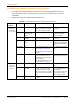
Table Of Contents
- Table of Contents
- Preface
- InterReach Fusion Wideband System Description
- System Overview
- System Hardware
- System OA&M Capabilities
- System Connectivity
- System Operation
- System Specifications
- RF End-to-End Performance
- 2100/1800 RAU (FSN-W1-2118-1)
- 2100 HP/1800 HP (FSN-W1-2118-1-HP)
- 2100 HP/2600 HP (FSN-W1-2126-1-HP)
- 2100 High Power RAU (FSN-W1-21HP-1)
- 1900/AWS RAU (FSN-W1-1921-1)
- 800/850/1900 RAU (FSN-W2-808519-1)
- 700/AWS RAU (FSN-W2-7021-1)
- 700/700 (Upper C) MIMO RAU (FSN-W2-7575-1)
- 700/700 (Lower ABC) MIMO RAU (FSN-W2-7070-1)
- 700 ABC/AWS HP/AWS HP RAU (FSN-W4-702121-1-HP)
- 700 UC/AWS HP/AWS HP RAU (FSN-W4-752121-1-HP)
- 850/1900 HP/AWS HP RAU (FSN-W5-851921-1-HP)
- 2500/2500 RAU (FSN-2525-1-TDD)
- 2600/2600 RAU (FSN-W3-2626-1)
- Fusion Wideband Main Hub
- Fusion Wideband Expansion Hub
- Remote Access Unit
- Designing a Fusion Wideband Solution
- Design Overview
- Downlink RSSI Design Goal
- Maximum Output Power Per Carrier
- 700/AWS RAU (FSN-W2-7021-1)
- 700 MHz (Upper C) MIMO RAU (FSN-W2-7575-1)
- 700 MHz (Lower ABC) MIMO RAU (FSN-W2-7070-1)
- 700 ABC/AWS HP/AWS HP RAU (FSN-W4-702121-1-HP)
- 700 UC/AWS HP/AWS HP RAU (FSN-W4-752121-1-HP)
- 800/850/1900 RAU (FSN-W2-808519-1)
- 850/1900 HP/AWS HP RAU (FSN-W5-851921-1-HP)
- 1900/AWS RAU (FSN-W1-1921-1)
- 2100/1800 RAU (FSN-W1-2118-1)
- 2100 HP/1800 HP RAU (FSN-W1-2118-1-HP)
- 2100 HP/2600 HP RAU (FSN-W1-2126-1-HP)
- 2100 High Power RAU (FSN-W1-21HP-1)
- 2500/2500 TDD RAU (FSN-2525-1-TDD)
- 2600 MHz MIMO RAU (FSN-W3-2626-1)
- Designing for Capacity Growth
- System Gain
- Estimating RF Coverage
- Link Budget Analysis
- Optical Power Budget
- Connecting a Main Hub to a Base Station
- Installing Fusion Wideband
- Installation Requirements
- Safety Precautions
- Preparing for System Installation
- Installing a Fusion Wideband Main Hub
- Installing a Fusion Wideband Main Hub in a Rack
- Installing an Optional Cable Manager in the Rack
- Installing a Main Hub Using the 12” Wall-Mounted Rack (PN 4712)
- Installing a Fusion Wideband Main Hub Directly to the Wall
- Connecting the Fiber Cables to the Main Hub
- Making Power Connections
- Optional Connection to DC Power Source
- Power on the Main Hub
- Installing Expansion Hubs
- Installing the Expansion Hub in a Rack
- Installing an Expansion Hub Using the 12” Wall-Mounted Rack
- Installing an Expansion Hub Directly to the Wall
- Installing an Optional Cable Manager in the Rack
- Powering on the Expansion Hub
- Connecting the Fiber Cables to the Expansion Hub
- Connecting the 75 Ohm CATV Cables
- Troubleshooting Expansion Hub LEDs During Installation
- Installing RAUs
- Configuring the Fusion Wideband System
- Splicing Fiber Optic Cable
- Interfacing the Fusion Wideband Main Hub to an RF Source
- Connecting a Fusion Wideband Main Hub to an In-Building BTS
- Connecting a Duplex Base Station to a Fusion Wideband Main Hub
- Connecting a Fusion Wideband Main Hub RF Band to Multiple BTSs
- Connecting a Fusion Wideband Main Hub to a Roof-Top Antenna
- Connecting a Fusion Wideband Main Hub to Flexwave Focus
- Connecting Multiple Fusion Wideband Main Hubs to an RF Source
- Connecting Contact Alarms to a Fusion Wideband System
- Alarm Monitoring Connectivity Options
- Replacing Fusion Wideband Components
- Maintenance and Troubleshooting
- Appendix A: Cables and Connectors
- Appendix B: Compliance
- Appendix C: Faults, Warnings, Status Tables for Fusion, Fusion Wideband, Fusion SingleStar
- Appendix D: Contacting TE Connectivity

Installing Fusion Wideband
Page 132 InterReach Fusion Wideband Installation, Operation, and Reference Manual
© 2015 TE Connectivity D-620616-0-20 Rev K • TECP-77-044 Issue 9 • March 2015
Troubleshooting Expansion Hub LEDs During Installation
• For all Expansion Hub with RAUs connected, the corresponding PORT LED should be
Green/Red, which indicates that the RAU is powered on and communication has been
established.
• The Expansion Hub
UL STATUS LED should be Green.
Table 93.
Troubleshooting Expansion Hub LEDs During Installation
During
Installation
LED State Action Impact
1 Expansion Hub
power is on
and no RAUs
are connected
POWER Off Check AC power; make sure the
Expansion Hub power-on switch is
on; replace the Expansion Hub.
The Expansion Hub is not
powering on.
PORT LEDs are on but didn’t
blin
k through
all
states.
Replace the Expansion Hub. The Microcontroller is not
resetting properly; flash
memory corrupted.
PORT Flashing Red
(6 PPM)
Port unusable; replace the
Exp
a
nsion Hub when possible.
Current sensor fault; do not
use the port.
UL STATUS Red, after power-up
blink
Replace
the Expansion Hub. The Expansion Hub laser is not
operational; no uplink between
the Expansion Hub and Main
Hub.
UL STATUS Red Check the Main Hub LEDs—refer to
Step 2 in
T
able 92 on page 126.
Use AdminBrowser to determine the
problem.
No communication with Main
Hub.
DL STATUS Red Check the downlink fiber for optical
power; v
erify that the cables are
connected to correct ports (that is,
uplink/downlink)
Check the Main Hub LEDs—refer to
Step 2 in
T
able 92 on page 126.
No downlink between the
Expansion Hu
b and Main Hub.
2 Expansion Hub
power is On
and RAUs are
connected
PORT Off Check the CATV cable. Power is not getting to the
RAU.
PORT Flashing Red
(60 PPM)
Test the CATV cable. If the cable
test
s OK, try another port. If the
second port’s LEDs are Red/Off,
replace the RAU. If the second RAU
doesn’t work; replace the Expansion
Hub.
Power levels to RAU are not
corr
ect; communications are
not established.
If the second port works, flag
the first port as unusable;
replace EH wh
en possible.
PORT Red Use AdminBrowser to determine the
problem.
RAU is off-line.