
User's Manual
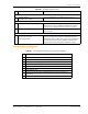


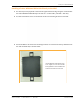


Table Of Contents
- Table of Contents
- Preface
- InterReach Fusion Wideband System Description
- System Overview
- System Hardware
- System OA&M Capabilities
- System Connectivity
- System Operation
- System Specifications
- RF End-to-End Performance
- 2100/1800 RAU (FSN-W1-2118-1)
- 2100 HP/1800 HP (FSN-W1-2118-1-HP)
- 2100 HP/2600 HP (FSN-W1-2126-1-HP)
- 2100 High Power RAU (FSN-W1-21HP-1)
- 1900/AWS RAU (FSN-W1-1921-1)
- 800/850/1900 RAU (FSN-W2-808519-1)
- 700/AWS RAU (FSN-W2-7021-1)
- 700/700 (Upper C) MIMO RAU (FSN-W2-7575-1)
- 700/700 (Lower ABC) MIMO RAU (FSN-W2-7070-1)
- 700 ABC/AWS HP/AWS HP RAU (FSN-W4-702121-1-HP)
- 700 UC/AWS HP/AWS HP RAU (FSN-W4-752121-1-HP)
- 850/1900 HP/AWS HP RAU (FSN-W5-851921-1-HP)
- 2500/2500 RAU (FSN-2525-1-TDD)
- 2600/2600 RAU (FSN-W3-2626-1)
- Fusion Wideband Main Hub
- Fusion Wideband Expansion Hub
- Remote Access Unit
- Designing a Fusion Wideband Solution
- Design Overview
- Downlink RSSI Design Goal
- Maximum Output Power Per Carrier
- 700/AWS RAU (FSN-W2-7021-1)
- 700 MHz (Upper C) MIMO RAU (FSN-W2-7575-1)
- 700 MHz (Lower ABC) MIMO RAU (FSN-W2-7070-1)
- 700 ABC/AWS HP/AWS HP RAU (FSN-W4-702121-1-HP)
- 700 UC/AWS HP/AWS HP RAU (FSN-W4-752121-1-HP)
- 800/850/1900 RAU (FSN-W2-808519-1)
- 850/1900 HP/AWS HP RAU (FSN-W5-851921-1-HP)
- 1900/AWS RAU (FSN-W1-1921-1)
- 2100/1800 RAU (FSN-W1-2118-1)
- 2100 HP/1800 HP RAU (FSN-W1-2118-1-HP)
- 2100 HP/2600 HP RAU (FSN-W1-2126-1-HP)
- 2100 High Power RAU (FSN-W1-21HP-1)
- 2500/2500 TDD RAU (FSN-2525-1-TDD)
- 2600 MHz MIMO RAU (FSN-W3-2626-1)
- Designing for Capacity Growth
- System Gain
- Estimating RF Coverage
- Link Budget Analysis
- Optical Power Budget
- Connecting a Main Hub to a Base Station
- Installing Fusion Wideband
- Installation Requirements
- Safety Precautions
- Preparing for System Installation
- Installing a Fusion Wideband Main Hub
- Installing a Fusion Wideband Main Hub in a Rack
- Installing an Optional Cable Manager in the Rack
- Installing a Main Hub Using the 12” Wall-Mounted Rack (PN 4712)
- Installing a Fusion Wideband Main Hub Directly to the Wall
- Connecting the Fiber Cables to the Main Hub
- Making Power Connections
- Optional Connection to DC Power Source
- Power on the Main Hub
- Installing Expansion Hubs
- Installing the Expansion Hub in a Rack
- Installing an Expansion Hub Using the 12” Wall-Mounted Rack
- Installing an Expansion Hub Directly to the Wall
- Installing an Optional Cable Manager in the Rack
- Powering on the Expansion Hub
- Connecting the Fiber Cables to the Expansion Hub
- Connecting the 75 Ohm CATV Cables
- Troubleshooting Expansion Hub LEDs During Installation
- Installing RAUs
- Configuring the Fusion Wideband System
- Splicing Fiber Optic Cable
- Interfacing the Fusion Wideband Main Hub to an RF Source
- Connecting a Fusion Wideband Main Hub to an In-Building BTS
- Connecting a Duplex Base Station to a Fusion Wideband Main Hub
- Connecting a Fusion Wideband Main Hub RF Band to Multiple BTSs
- Connecting a Fusion Wideband Main Hub to a Roof-Top Antenna
- Connecting a Fusion Wideband Main Hub to Flexwave Focus
- Connecting Multiple Fusion Wideband Main Hubs to an RF Source
- Connecting Contact Alarms to a Fusion Wideband System
- Alarm Monitoring Connectivity Options
- Replacing Fusion Wideband Components
- Maintenance and Troubleshooting
- Appendix A: Cables and Connectors
- Appendix B: Compliance
- Appendix C: Faults, Warnings, Status Tables for Fusion, Fusion Wideband, Fusion SingleStar
- Appendix D: Contacting TE Connectivity

Installing a Fusion Wideband Main Hub
InterReach Fusion Wideband Installation, Operation, and Reference Manual Page 119
D-620616-0-20 Rev K • TECP-77-044 Issue 9 • March 2015 © 2015 TE Connectivity
Cleaning the Fiber Ends
Be sure that the fiber cable’s SC/APC connectors are clean and free of dust and oils. You need
lint-free cloths, isopropyl alcohol, and compressed air.
1 Moisten a lint-free clot
h with isopropyl alcohol.
2 Gently wipe the
fiber end with the moistened cloth.
3 Using a dry lint-free cloth, gently wipe the fiber end.
4 Spray the compressed air away from the
connector for a few seconds to clean out the nozzle
and then use it to completely dry the connector.
Testing the Fiber Cables
Perform cable testing and record the results. Test results are required for the final As-Built
Document.
Connecting the Fiber Cables
The fiber cable is labeled with either 1 or 2, or is color-coded. In addition to these labels, you
should add a code that identifies which port on the Main Hub is being used and which Expansion
Hub the cables are intended for. This differentiates the connectors for proper connection between
the Main Hub and Expansion Hubs.
For example:
First pair to Main Hub port 1: 11
(uplink), 12 (downlink);
Second pair to Main Hub port 2: 21 (uplink), 22 (downlink);
Third pair to Main Hub port 3: 31 (uplink), 32
(downlink); and so on.
NOTE: The Fusion Wideband One Port Main Hub (PN: FSN-1-MH-1P and FSN-2-MH-2-1P) configuration
is a cost reduced version of the Fusion Wideband Main Hub and supports only one Expansion Hub
(up to 8 RAUs).
If the fiber jumper is labeled with 1 or 2
1 Connect 1s to UPLINK ports on the Main Hub.
2 Connect 2s to DOWNLINK ports on the Main Hub.
3 Record which cable number and port number you
connected to UPLINK and DOWNLINK.
(This information is needed when connecting the other end of the fiber cable to the Expansion
Hub’s fiber ports.)
The fiber port LEDs should be off,
indicating that the Expansion Hub(s) are not connected.