
User Manual
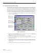


Table Of Contents
- SECTION 1: Overview
- SECTION 2: Description
- SECTION 3: Host Unit Installation
- SECTION 4: Operation
- SECTION 5: Maintenance
- SECTION 6: General Information
- ABOUT THIS MANUAL
- RELATED PUBLICATIONS
- ADMONISHMENTS
- GENERAL SAFETY PRECAUTIONS
- STANDARDS CERTIFICATION
- LIST OF ACRONYMS AND ABBREVIATIONS
- SECTION 1: Overview
- SECTION 2: Description

ADCP-75-116 • Issue A • August 2001 • Section 4: Operation
Page 4-15
©
2001,
ADC
Telecommunications,
Inc.
Figure 4-11. Remote Fwd Att Pop-Up Screen
5. Enter
the
required
attenuation
value
and
click
OK
to
close
the
pop-up
screen
and
to
make
the
changes
take
effect.
6. Verify
that
the
appropriate
RF
output
signal
level
appears
in
the
RF
Pwf-VSWR
Low
section
(see
Figure 4-10).
2.8 Enter Host Reverse Attenuation
The
level
of
the
RF
signal
that
should
be
input
to
the
BTS
will
vary
depending
on
the
type
of
BTS
and
the
number
of
channels
present.
To
interface
with
the
BTS,
the
reverse
path
signal
level
must
be
adjusted
to
provide
the
signal
level
required
by
the
BTS.
The
HU
provides
from
0
to
30
dB
of
gain
in
the
reverse
path.
Use
the
following
procedure
to
set
the
reverse
path
gain:
1. Check
the
BTS
manufacturer’s
specifications
to
determine
the
composite
signal
level
required
at
the
BTS
reverse
path
input
port.
Table 4-2. Maximum Composite Output Signal Levels
NUMBER OF
CHANNELS
MAXIMUM OUTPUT
SIGNAL LEVEL
137
dBm
240
dBm
341
dBm
443
dBm
544
dBm
6
or
more 45
dBm
Note:
To
comply
with
Maximum
Permissible
Exposure
(MPE)
requirements,
the
maximum
composite
output
from
the
antenna
cannot
exceed
1000
Watts
EIRP
and
the
antenna
must
be
permanently
installed
in
a
fixed
location
that
provides
at
least
6
meters
(20
feet)
of
separation
from
all
persons.