
User Manual
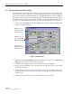


Table Of Contents
- SECTION 1: Overview
- SECTION 2: Description
- SECTION 3: Host Unit Installation
- SECTION 4: Operation
- SECTION 5: Maintenance
- SECTION 6: General Information
- ABOUT THIS MANUAL
- RELATED PUBLICATIONS
- ADMONISHMENTS
- GENERAL SAFETY PRECAUTIONS
- STANDARDS CERTIFICATION
- LIST OF ACRONYMS AND ABBREVIATIONS
- SECTION 1: Overview
- SECTION 2: Description

ADCP-75-116 • Issue A • August 2001 • Section 4: Operation
Page 4-14
©
2001,
ADC
Telecommunications,
Inc.
2.7 Enter Remote Forward Attenuation
The
STM
internal
forward
path
attenuator
setting
is
used
to
fine
tune
or
reduce
the
power
level
of
the
composite
output
signal
level
at
the
STM
antenna
port.
The
maximum
composite
output
signal
level
at
the
STM
antenna
port
is
set
using
the
Host
internal
forward
attenuator
(see
Section
2.4).
However,
component
variations
may
result
in
the
output
power
at
the
STM
antenna
port
being
slightly
above
or
below
the
specified
maximum
of
5
watts
per
channel.
If
this
is
the
case,
the
STM
forward
attenuator
may
be
used
in
conjunction
with
the
Host
forward
attenuator
to
add
or
remove
attenuation
to
produce
the
required
output
signal
level.
If
less
power
than
the
maximum
of
5
watts
per
channel
is
required,
the
STM
forward
attenuator
may
be
used
to
reduce
the
power
level
to
the
specified
level.
The
default
setting
is
0
dB.
Use
the
following
procedure
to
change
the
STM
forward
attenuation:
1. Click
on
the
REMOTE
PA
tab.
The
REMOTE
PA
display
will
open
within
the
EMS
main
window
as
shown
in
Figure 4-10.
Figure 4-10. REMOTE PA Display
2. Check
the
level
of
the
RF
output
signal
(as
determined
in
Section
2.6)
against
the
values
shown
in
Table 4-2.
3. Determine
if
more
or
less
attenuation
is
required
to
produce
the
required
output
signal
level.
4. Right-click
on
the
Remote
Fwd
Att
section
of
the
display
(see
Figure 4-10).
The
Remote
Fwd
Att
pop-up
screen
will
open
as
shown
in
Figure 4-11.
Note:
To
comply
with
Maximum
Permissible
Exposure
(MPE)
requirements,
the
maximum
composite
output
from
the
antenna
cannot
exceed
1000
Watts
EIRP
and
the
antenna
must
be
permanently
installed
in
a
fixed
location
that
provides
at
least
6
meters
(20
feet)
of
separation
from
all
persons.
Right-click here to
open the Remote Fwd
Att pop-up screen
RF output signal level