
User Manual
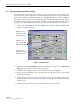


Table Of Contents
- SECTION 1: Overview
- SECTION 2: Description
- SECTION 3: Host Unit Installation
- SECTION 4: Operation
- SECTION 5: Maintenance
- SECTION 6: General Information
- ABOUT THIS MANUAL
- RELATED PUBLICATIONS
- ADMONISHMENTS
- GENERAL SAFETY PRECAUTIONS
- STANDARDS CERTIFICATION
- LIST OF ACRONYMS AND ABBREVIATIONS
- SECTION 1: Overview
- SECTION 2: Description

ADCP-75-116 • Issue A • August 2001 • Section 4: Operation
Page 4-13
©
2001,
ADC
Telecommunications,
Inc.
Figure 4-9. Host Fwd Delay Pop-Up Screen
2.6 Determine Output Signal Level at STM Antenna Port
The
RF
output
signal
level
should
be
measured
at
the
STM
ANTENNA
port
to
verify
that
maximum
composite
signal
level
does
not
exceed
5
watts
per
channel.
Use
the
following
procedure
to
verify
if
the
power
level
is
at
the
required
level:
1. Verify
that
RF
ON/OFF
switch
on
the
LPA
in
the
OFF
position.
2. Disconnect
the
antenna
cable
from
the
STM
ANTENNA
port.
3. Connect
a
spectrum
analyzer
or
RF
power
meter
to
the
STM
ANTENNA
port.
(Check
the
input
rating
of
the
test
equipment
and
insert
a
PAD
if
necessary.)
4. Place
the
RF
ON/OFF
switch
on
the
LPA
in
the
ON
position.
5. Measure
the
RF
level
of
a
single
carrier,
such
as
the
control
channel,
in
dBm.
Make
sure
the
resolution
bandwidth
of
the
spectrum
analyzer
or
power
meter
is
narrow
enough
to
measure
the
power
of
the
single
30
kHz
channel
only.
6. Calculate
the
total
composite
signal
power
using
the
following
formula:
P
tot
=
P
c
+
10Log
N
Where,
P
tot
is
the
total
composite
power
in
dBm
P
c
is
the
power
per
carrier
in
dBm
as
measured
in
step
2,
and
N
is
the
total
number
of
channels.
7. Record
the
result
calculated
in
step
6.
8. Place
the
RF
ON/OFF
switch
on
the
LPA
in
the
OFF
position.
9. Disconnect
the
spectrum
analyzer
or
RF
power
meter
from
the
STM
ANTENNA
port.
10. Re-connect
the
antenna
cable
to
the
STM
ANTENNA
port.