
User Manual

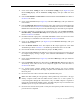

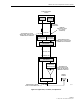
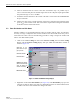


Table Of Contents
- SECTION 1: Overview
- SECTION 2: Description
- SECTION 3: Host Unit Installation
- SECTION 4: Operation
- SECTION 5: Maintenance
- SECTION 6: General Information
- ABOUT THIS MANUAL
- RELATED PUBLICATIONS
- ADMONISHMENTS
- GENERAL SAFETY PRECAUTIONS
- STANDARDS CERTIFICATION
- LIST OF ACRONYMS AND ABBREVIATIONS
- SECTION 1: Overview
- SECTION 2: Description

ADCP-75-116 • Issue A • August 2001 • Section 4: Operation
Page 4-10
©
2001,
ADC
Telecommunications,
Inc.
Figure 4-6. HOST RF Display
2. Right-click
on
the
Host
Fwd
Att
section
of
the
display
(see
Figure
4-6).
The
Host
Fwd
Att
pop-up
screen
will
open
as
shown
in
Figure 4-7.
Figure 4-7. Host Fwd Att Pop-Up Screen
3. Obtain
the
value
of
the
baseline
total
composite
input
signal
level
as
determined
in
step
10
of
Section
2.2.
4. Refer
to
Table 4-1
to
determine
the
appropriate
value
to
enter
for
the
Host
forward
path
attenuator.
Note
that
the
correct
entry
is
determined
by
both
the
number
of
channels
the
system
will
transport
and
the
baseline
total
composite
input
signal
level.
5. Enter
the
attenuation
value
and
click
OK
to
close
the
pop-up
screen
and
to
make
the
changes
take
effect.
Right-click here
to open Host Fwd
Att pop screen