
User Manual


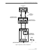
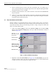


Table Of Contents
- SECTION 1: Overview
- SECTION 2: Description
- SECTION 3: Host Unit Installation
- SECTION 4: Operation
- SECTION 5: Maintenance
- SECTION 6: General Information
- ABOUT THIS MANUAL
- RELATED PUBLICATIONS
- ADMONISHMENTS
- GENERAL SAFETY PRECAUTIONS
- STANDARDS CERTIFICATION
- LIST OF ACRONYMS AND ABBREVIATIONS
- SECTION 1: Overview
- SECTION 2: Description

ADCP-75-116 • Issue A • August 2001 • Section 4: Operation
Page 4-8
©
2001,
ADC
Telecommunications,
Inc.
8. Select
an
attenuator
that
is
as
close
to
the
value
calculated
in
step
7
as
possible.
Try
to
select
a
value
that
will
place
the
baseline
signal
level
of
the
composite
input
signal
within
the
preferred
range
of
–25
to
–35
dBm.
9. Install
the
external
attenuator
in
the
coaxial
cable
that
is
connected
to
the
FORWARD
RF
IN
port
at
the
HU.
10. Subtract
the
value
of
the
external
attenuator
used
in
step
9
from
the
total
composite
signal
power
(P
tot
)
and
record
the
result.
This
value
will
be
required
when
setting
the
attenuation
of
the
HU’s
internal
forward
attenuator.
2.3 Enter Site Number and Site Name
All
HU’s
and
RU’s
are
programmed
with
the
same
site
number
and
site
name.
It
is
therefore
necessary
to
assign
a
unique
site
name
and
site
number
to
the
HU
and
RU
before
they
can
be
connected
to
the
same
CAN.
Use
the
following
procedure
to
assign
a
unique
site
number
and
name
to
each
HU
and
RU
system:
1. Click
on
the
HOST
Config
tab
and
on
the
REMOTE
Config
tab.
The
HOST
Config
display
and
the
REMOTE
Config
display
will
open
within
the
EMS
main
window
as
shown
in
Figure 4-4.
Figure 4-4. HOST and REMOTE Config Displays
2. Right-click
on
the
HOST
Site
Number
(see
Figure 4-4).
The
Site
Number
pop-up
screen
will
open
as
shown
in
Figure
4-4.
Enter
any
odd
number
between
33
and
61
and
then
click
on
OK
to
close
the
screen
and
make
the
changes
take
effect.
HOST Site Number
HOST Site Name
REMOTE Site Number
(Entered automatically
when the HOST site
number is selected)
REMOTE Site Name
Right-Click on the
point shown to open
pop-up screen